

Tutorial: How to model a BBS LM wheel in Solidworks and show design intent.

Well here it is:
-
Step 1:
THE MOOD:
This is probably the hardest step. Choose some good tunes to help you concentrate on the task at hands. After setting some good vibe, the rest should be a breeze.

-
Step 2:
THE SETUP:
Fire Solidworks. I will be using Solidworks 2012 throughout this tutorial. I don't think I will use any recent functionality so I believe older versions can follow along. Now, we will setup our profile_blueprint. But first we have to agree on the size of the wheel we will model. For no other reason than because I like the number, I will model a 20'' diameter wheel. Because the way the blueprints were made, this means that the depth of the wheel will be 10''. So, on the right plane draw a 10'' square, with the lower left vertex on the origin. Note that I work with the MMGS unit system, but Solidworks is so cool that I can write, in the Smart Dimension textbox, "10 in" and it will display "254 mm", as it should (1'' = 25.4 mm).

-
Step 3:
Now, still in the same sketch, go to "Tools->Sketch Tools->Sketch Picture...".

-
Step 4:
In the search box that pops-up, navigate to the folder "bbs_lm_tutorial_references" and select the profile_blueprint.jpg image. It will be too big:

-
Step 5:
So scale it down and adjust it until its revolution axis matches the lower line of the square, and it fits inside that same square.

-
Step 6:
Ok, now just delete the square.
"Wha... wha... wha... what???".
Yeah you don't need it anymore, so delete those extra lines that may, if left in place, confuse you down the path. Besides, it may save you some extra kbs of hard disk space, when you save your file.See what I did here? I subtly warned you to save your file. I can't stress this enough: save your files often. Don't rely on Solidworks autosaves. Also, make some backups to other devices, preferably to some online storage device (Dropbox), so that even if your physical hardware goes kaput, you can still have access to your hard modeled parts.
-
Step 7:
FIRST SKETCHES:
Now we start drawing some lines in the Right plane, to resemble the profile_blueprint. Let's focus, for now, on the barrel of the wheel (the blue part: a bad color choice I admit, given that sketch lines are also blue by default). I never, ever, try to match the profile to its final form, simply because Splines are too hard (if not impossible, by hand) to setup. If you increase the number of points of the Spline it will lose "smoothness" (if you right mouse click on the Spline->Show Curvature Combs, those Combs will show some funky variations/transitions). So I simply use 3 or 4 points splines for each major surface of the barrel, and I let them end abruptly, where they should have a nice radius. I will, later, blunt this hard edge with the "Fillet" feature.
Where should we place the point where two Splines meet each other? This is one of those questions whose answer is just: practice makes perfect. What I do is place it somewhere halfway the arc that I want to create (in this case we have a guide so it's easy to see where halfway is) and NOT on the line. How far away from the line? I don't use a scientific approach, I just guess and if I am far off I just go back and readjust.

-
Step 8:
Oh crap. We can't see anything. I really need to change the colors of this blueprint. However, sometimes our job will require us to use some drawing whose colors can't be easily changed, so let's just change the colors of the sketch lines in Solidworks. Go to "Tools->Options..." and in the first tab "System Options" go to "Colors" and scroll down until you see "Sketch, Fully Defined" and "Sketch, Under Defined". Change those colors to any other that's easier to see.

-
Step 9:
I chose pink, because I am fabulous.

-
Step 10:
I like to keep these splines untrimed, and start a new sketch in the right plane, where I convert the splines I just layed, and then I trim 'em suckers.Why? Because I find it easier to go back and reajust untrimed splines (if I need to).

-
Step 11:
Note that I hide the second sketch (untrimed splines) because I don't need it anymore (I will keep it though because I may want to do some fine tuning, to the shape of the barrel, in the future). Right mouse click over the name of the sketch to hide (in the Feature tree) and:

-
Step 12:
THE BARREL:
Now we simply insert a (an?) horizontal construction straight line coincident with the origin (it doesn't matter its lenght), in the Sketch 3, to serve as a revolution axis. Have you ever notice that wheels are, essentially, solids of revolution?

-
Step 13:
We can, now, make a revolution of our profile. Solidworks just calls it a Revolve operation.

-
Step 14:
Now look at your accomplishment. It sucks. Those hard edges would, besides look silly, cut your hand right off of your arm. That wouldn't be pleasant. Oh, and they would be stress concentration regions (huge no-no). So what do you do? Fillets. Fillets everywhere. But there is a neat trick I like to use. Instead of using a constant radius fillet, I like the face fillet with the "Curvature continuous" box checked.

-
Step 15:
This fillet will be curvature continuous (no s**t) which will make your zebras a lot nicer (which in turn will make your render a lot better because the reflections will be continuous and a lot closer to the way light behaves in the real world.) The values you use for each fillet are up to you. I just use values that allow the barrel to match the profile_blueprint.

-
Step 16:
Hell yeah! Now this is goo... acceptable-ish. Why? Because we are missing the thingy (technical term) where the face plate bolts to the barrel. It is there in the profile_blueprint, why didn't I draw it from the beginning? Because of reasons. No, not really. I just forgot about it. So let's model that face. It's pretty straightforward, and it's another solid of revolution, which we want to merge to the already modeled barrel (so leave that checkbox on).

-
Step 17:
Some more fillets, et voilà:

-
Step 18:
Pretty cool uhm? Let's just do a little experiment, you will understand in a minute the purpose of it. Start another Sketch on the Right Plane and click on "Intersection Curve":

-
Step 19:
Now select every single face of the barrel. It is a PITA but now you get to understand the importance of step 1. After you selected all those surfaces you should have 2 profiles:

-
Step 20:
Delete the bottom one (or the top one if you are irreverent and will not do as I say), and add another horizontal construction straight line coincident with the previous rev. axis. Now the fun part: select the profile which you didn't eliminate (every single line: here you can just make a selection rectangle with your mouse, around the profile, and it will select them all) and go to "Tools->Spline Tools->Fit Spline...":

-
Step 21:
and lower that tolerance (aka: increase the number, engineers are funny guys), check "Delete geometry" and uncheck the 3 bottom ones:

-
Step 22:
You are left with a profile composed of a single Spline. I dare you, I double dare you (no curse words allowed I guess) to achieve this result by fine tuning a Spline by hand. Don't try it. The software has the tools for a reason. Be smart.
Now revolve this Spline, unchecking "Merge result". The resultant solid is in the same place as the previous barrel. Let's fix this. Go to "Insert->Features->Move/Copy...":

-
Step 23:
and select the newly created solid. Drag it to some place so that you can see both solids:

-
Step 24:
Note how the new barrel has only 1 surface. Go to the "Evaluate" tab and choose "Curvature":

-
Step 25:
Note how the new barrel is smoother than the old one:

-
Step 26:
You can even run some "Zebra Stripes" to further confirm this. So, all of this for what? To teach you a neat trick to produce smoother models. All of what we did so far, was to model the barrel. Since the barrel is just a solid of revolution without any other detail (except the air valve hole) if we managed, from the beginning, to draw this last profile, we wouldn't need to go through all this trouble. So let's do just that. Copy this single Spline, and the rev. axis, open a new file, select the Right Plane and paste (you should get it align as the previous part, with the start of the rev. axis on the origin, if you didn't don't worry just keep reading):

-
Step 27:
Revolve the hell out of that Spline:

-
Step 28:
Presto. You got yourself a nice, smooth BBS LM barrel. Do you want to see an interesting thing? Compare the file sizes of both the barrel modeled with all those fillets, and this new part with just a single Revolve. I saved a MB in my pc.
-
Step 29:
THE FACE PLATE - REVOLVE PROFILE:
Well, this is pretty much the same as the barrel. You can start, however, by copying the first part, the barrel modeled with all the fillets, rename it to your liking, open it and delete every feature except the first sketch, where you have the profile_blueprint already setup.
Once again, draw some "simple" (as in, with as few points as possible) Splines to somewhat resemble the blueprint. You can, of course, throw in some dimensions, but don't worry too much about it:

-
Step 30:
Note I didn't draw the center hole (for the center cap). I didn't forget about it. I just like to leave it to the end so that I can model it using extruded cuts (I don't like drawings with a lot of lines, if possible I try to use a greater number of sketches with a fewer number of splines each. I can't really say that this improves performance, or is in fact recommended, I just like to work with less lines). When you have a shape you like, revolve it:

-
Step 31:
Now you just have to detail this face plate. In fact this is probably the step that separates men from boys. If there's something about good renders it's in the details. "The devil's in the details". There's not much more about it than good details. For that you have to look at reference images (I hope you have been looking to reference images up so far, I am just reminding you) and see how the final product looks. Study your subject. Don't rush it. Well, you can rush it, but don't call yourself an engineer or a designer please. Take your time, it's not like you are at gunpoint and have to finish this model by yesterday (ehm.. just to make sure, you aren't right?). But who the hell am I? Let's move on.
Now you should cut the center cap hole. You can use Cut-Extrudes for the ends and a Cut-Revolve for the inner middle section (this is just basic modeling, go ahead do some experiments be wild mate):

-
Step 32:
This is where you can see that my blueprints are not perfect. Would anybody design a region, where the hooks of the center cap will engage, in a wedge shape?

-
Step 33:
Doubtful, but from the reference images that's how it looks is real life. But oh well, I have to control my OCD, and be happy with this. Furthermore I will not shot a render from the backside of this wheel, so I guess things can work out. Now, some more curvature continuous fillets and some chamfers and you get:

-
Step 34:
Perinawa (means nice, and it's a word from the Himba tribe). One small note, I like to fillet the hard edges left by the chamfer operation, simply because in real life those sharp edges are blunted to protect the person who will handle the wheel and to reduce stress concentration factors (once again). With the filleting of these hard edges, our renders come out way, way nicer.

-
Step 35:
Sometimes a simple fillet with a 0.5mm radius is the difference between a good render and a "Jesus F. Christ" render.
Once we are happy with the shape, we will do the same steps, as for the barrel, to produce a solid of revolution with just one surface:

-
Step 36:
Crab. Our rev. axis doesn't start at the origin. When we select both entities to move them at the same time, we see that if we try to drag them from a point,only the entity to which the point belongs is dragged. If, however, we drag them starting from the middle of any line, both entities are dragged. Does this seems logic? So we are stucked. No we are not.
The software has this cool feature called "block" that we will use. Right now. Right click near the drawing and select "Make block":

-
Step 37:
Select both entities (the spline and the axis) and bam. Select anything, and both entities are now dragged at the same time. Awesome. To make said entities return to their normal behavior, right click on any one of them and click "Explode block":

-
Step 38:
Está feito. Now they are positioned where we wanted (we didn't really need the rev. axis start coincident with the origin, but now you know how).
Revolve it. Admire it. Save it.
Time for a coffee. -
Step 39:
THE FACE PLATE - FRONTAL CUTS:
Our wheel looks pretty good at the moment. Almost like an old Group B car wheel ("yeah you wish!").

-
Step 40:
But we set ourselves (I did actually, you did the moment you kept following this tutorial) to model a BBS LM. So we need to keep going. We will now cut its most emblematic feature, and perhaps what will make it look like a proper BBS LM wheel, its spokes. On the Front Plane, start a new Sketch and insert the face_blueprint image from the references folder.

-
Step 41:
Adjust and scale the image so that the center cap in the image and the center cap hole match. Use the transparency option to help you position the image correctly:

-
Step 42:
Now take a good look at the image. It's a repeating pattern. And we can figure out we will use some fillets. Instead of modeling all the spokes at once, and applying the fillets to every one of them (I was never able to correctly use a "Circular Pattern" for features. It works great for bodies and surfaces, but for features
it works when it wants to), we can model one spoke and circular pattern it 10 times (10 spokes). So we don't really need a solid of revolution of 360º. Well, let's delete that feature then, and apply a revolution of
18º.
-
Step 43:
As you can see from the reference images the cuts for the spokes draft inwards. What I mean is that those 10 triangles (and those 10 U's) are bigger if seen from the front than from the back, so we need to do this. How? Once again, Solidworks has this candy feature called "Draft angle" in the Extrude and Cut-Extrude dialog boxes. We will make use of it. But now, create a new plane, parallel to the frontal one and really close to the face plate:

-
Step 44:
In this new plane, draw some straight lines and circles to loosely match the frontal cuts for the spokes. Don't break a sweat for this.

-
Step 45:
Apply a mirror and then a circular sketch pattern to the lines and circles just drawn (so that the draft feature will work correctly):

-
Step 46:
And Cut-Extrude this bad-boy. You have to balance the draft angle and the depth to achieve nice results:

-
Step 47:
This is what we get:

-
Step 48:
It's pretty obvious that we need some fillets. However to help ourselves, let's mirror our part twice:

-
Step 49:
And now for some fillets. But don't go crazy. We will cut the mirrors we just created, so only fillet what will stay after the cut:

-
Step 50:
Yeah, cut it:

-
Step 51:
Some more fillets:

-
Step 52:
And a mirror with the "Knit surfaces checked":

-
Step 53:
It starts to look half-decent. But now we need to do a circular pattern. Problem is: we have no circular line to select. We have to create a split-line on our model. Where? That's basically irrelevant.

-
Step 54:
Go nuts:

-
Step 55:
We can now use our split line to produce a circular pattern:

-
Step 56:
To join all those bodies in a single body use the "Combine" feature in the "Add" mode:

-
Step 57:
Select the 10 bodies and boom:

-
Step 58:
A BBS LM face plate al dente.
Does it start looking like a wheel?
-
Step 59:
I believe so.
-
Step 60:
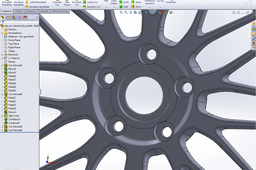
THE FACE PLATE - DETAILS:
Ok, let's wrap our work. Beginning with the lugnuts holes, "cut-extrude" "through all" a smaller diameter hole, and "cut-extrude" until the middle of the face plate a bigger diameter hole.

