Understanding Design & Process of DMLS 3D Metal Printing

Over the last decade, metal 3D printing has seen significant growth and evolution in the additive manufacturing landscape. Major players like NASA and GE have incorporated additive metals into their programs, aided by industry-wide material development and process research. Additive metal parts are seen more and more in end-use production.
This tutorial covers Direct Metal Laser Sintering (DMLS) design constraints and freedoms, available metal materials and the process controls that deliver incredible metal parts.
-
Step 1: Materials and Alloys Available for Metal 3D Printing
- Steel
- Copper
- Stainless steel
- Titanium (pure)
- Titanium alloys
- Aluminum alloys
- Nickel-based alloys
- Cobalt chrome alloys
-
Step 2: Design Affects Performance
During build, Direct Metal Laser Sintering (DMLS) parts are anchored to a build platform. About 6mm of support material is built around parts so that parts can be removed cleanly via machining. DMLS uses a very powerful laser to micro meld powdered metals layer-by-layer. Delicate geometry features will burn and distort from the heat of the laser if they are unsupported. Learn how to factor in supports and angles to minimize support structures and optimize your design for DMLS in the next step.
-
Step 3: Angles
STL editors will automatically generate support structures in your design, but you can manually refine the structures prior to build. Support material is the same metal as the final part, and requires labor to remove. Typically with DMLS, features below 45 degrees require support structures, and 60 degree angles are ideal.
In the image below, the open box design (left) is intended to allow ample cooling for interior components. It has a large and downward facing surface. With the DMLS process its downward facing surface will warp or burn out without extensive support structures (shown right in blue).

Solution
One solution to minimize supports: exchange the flat downward facing surfaces for an angled, saw-blade configuration. In the image below, the saw-blade design reduces supports by offering a surface with degree variances that aid in the sintering process. The new design cuts support removal time in half which reduces overall build time.

-
Step 4: Finishing
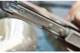
DMLS parts can be hand polished to result in ideal surface finishes and machined to meet critical engineering tolerances. The surface of a DMLS part as-built is ~350 Raμ inch. Media blasting will smooth surfaces to 98-236 Raμ inch, while a tumbled finish will further ameliorate surfaces to 32-124 Raμ inch. Hand polishing is more ideal for one-off unique parts that require a very specific surface quality.

-
Step 5: Get More Details
For full details on Direct Metal Laser Sintering, including further design guides download the white paper, Getting the Most Out of Metal 3D Printing.

