

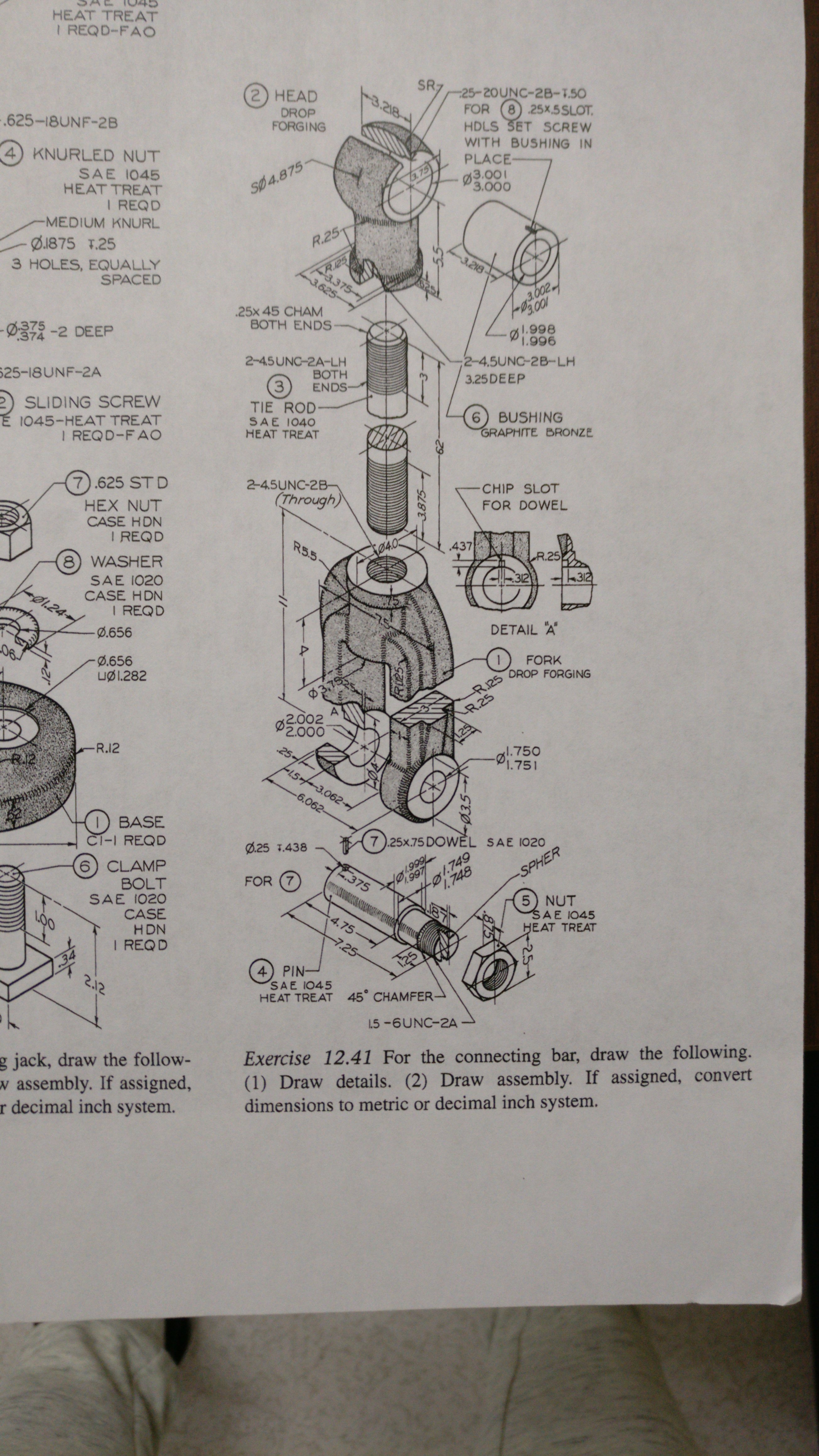
How to model this Fork from Connecting bar Assembly?

FORK part.
To anyone that will provide a solidworks file or by 2d orthographic sketch using autocad. I will donate cash.. I need this immediately. Thanks.

9 Answers

Richard,
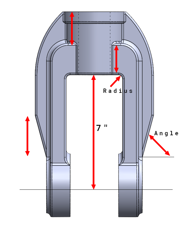
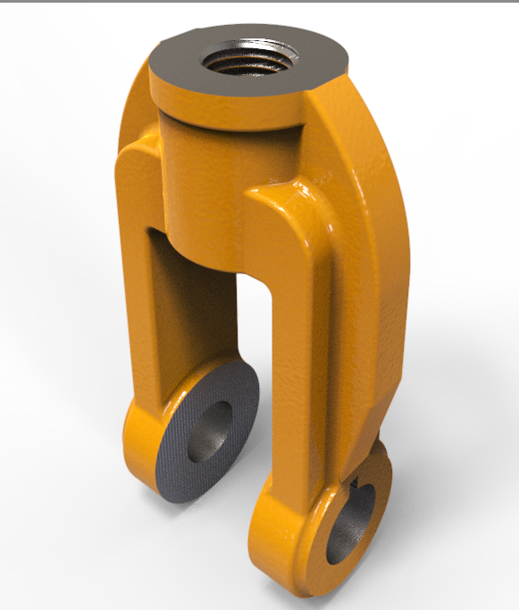
I've attached an image with some unknown dimensions. All of the dimensions are not needed, I think most of them could be determined if just one were provided.
Same with the angle unit. Given either the angle, or the length of the slope, the other can be determined. I took a guess and went with 15° (or 75° depending on where it is measured from).
I centered the rectangular protrusion on the height of the central cylindrical boss, but it is only a guess without a value in the drawing (or method to calculate it). Hopefully I am just missing something obvious.
Using your method of overall length (11"), and the radius of the bottom cylindrical boss (2"), I've updated the image to show one of the values.
Orthographic views in DWG format.
These seem less useful than nearly any other format, but I'll assume you know what you are doing with them.
As I mentioned above, some of the dimensions are guesses. I don't see a means to calculate the actual values from what is provided.

Here's how I interpreted the missing part on the side of the arm, as a tangent curve as opposed to an angled elbow. I'm not sure what I did but the armpit radius was not needed for me because the distance between the arms is slightly less than the diameter of the bottom of that upper cylindrical boss. That is to say, although I didn't use the sweep command, I swept the 1" dimension up along the shoulder of the 3x1 rib rib, and projected the .25 offset from beneath.

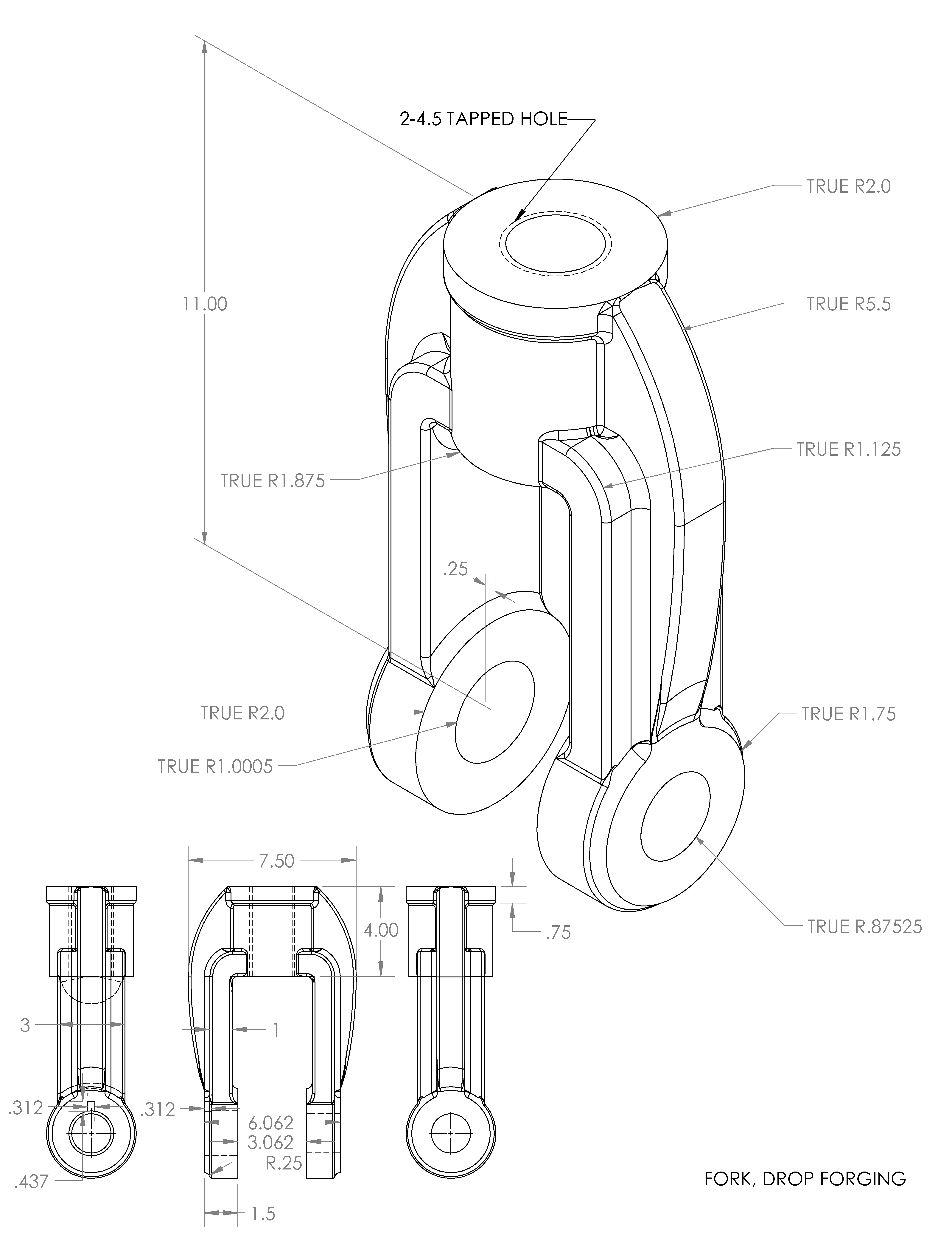


A revised drawing with different edge options. Also a step file.
hey guys,
I am doing this as a project in class and I'm having trouble with this fork part, I would really appreciate it if I could get an sldprt part.
Also I made the head part of this same assembly and it doesn't look right.
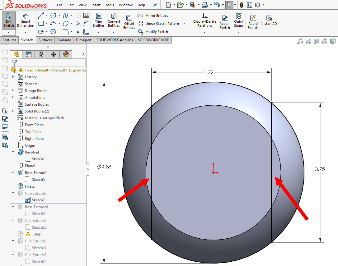
The diameter of the cylinder under the spherical piece is larger than the width of the cut sphere (3.375>3.218).
(No threads needed)
Thanks in advance for the help.
MyNameJeff,
Your model looks good. the only things I'd change:
* Wait until the end to apply the fillets
* Boss4 makes no sense, just edit the depth of cut9 instead.
As you pointed out, the cylinder under the sphere does not look correct, but the dimensions look fine. I'm not sure what the error is yet, but look at Sketch7. Somehow the two profiles you are cutting with are not the same. See my attached image. The profile on the left is almost twice as big as the profile on the right. I'd redraw this as a rectangle, centered on the origin. There is no need to draw arcs in this sketch, or use multiple profiles.
The fork model is here: https://grabcad.com/library/request-fork-drop-forging-1
The drawing appears to be missing a dimension or two.
The "depth" of the fork is not called out. The overall length of the part can be determined from the 11" dimension, but I don't see how/where the distance from the axis of the 2" holes to the "bottom" of the 3.75" diameter shaft (with the internal threads).
Also, what angle do you suppose the sides taper in at? It is 7.5" at the widest, but that slopes down to 6.062"
I don't see an angle dimension, or a distance value for the length of the taper.
Anyone else see a way to calculate the distance(s)?
I took some guesses on what I see as missing dimensions. The results can be seen below. Let me know if there is additional information or dimensions to eliminate the need for guessing.

Richard,
That looks great. Maybe we'll never know how to interpret the drawing "correctly", but I'd give us a B+ for getting quite close (assuming that we are not correct).
It would be a pretty devious course if the instructor assigned drawings which required guesswork. They could call it Real World Design.
My least favorite "drawings" from customers are hand drawn ones with units (often mixed units). The really great ones are not drawn to scale, so I have to ask them "Should I model this shape as it is drawn, or should I model this shape based on the dimensions provided?"
I like your rough cast texture.
Regards,
