

How to Create Variable Density FDM 3D Printed Parts

A unique characteristic of FDM technology is that a single part can have regions with different build styles, which can be used to make a part with variable densities. With just a few minutes of extra design and pre-processing, you can save hours of build time and/or dramatically improve the part’s properties.
-
Step 1: About Variable Density Parts
Unlike default interior styles, such as solid or sparse that are applied to the entire part, variable densities allow a single part to have combinations of solid and sparse fill styles, and each region’s density can be adjusted independently (Figures 1 and 2).

Figure 1

Figure 2
The advantages of variable density parts are:
• Optimized strength, weight and performance
• Reduced build time and cost
• Enable niche applications (e.g., end-use parts, fiber molding and thermoforming)
Variable density parts are created using a combination of 3D computer-aided design (CAD) and InsightTM software. For complete control over each region, the 3D CAD model is split into sub-components and each may have a unique density. Each subcomponent is processed with different toolpath options (Figures 3 and 4). The use of variable density is common when optimizing a design for functionality. For example, solid fill is used where additional strength is needed, while the remainder of the part is built using sparse fill.

Figure 3

Figure 4
-
Step 2: Tools & Supplies
- 3D Computer-Aided Design (CAD) Software
- Insight software
-
Step 3: Modify the CAD Model
Step A: Open the CAD model to be produced with variable densities (Figure 5).

Figure 5
Step B: Add a reference feature (square extrusion) at the origin making it slightly taller than the part. This will assist with alignment of the various regions within the Insight software (Figure 6).

Figure 6
Step C: Save the model.
Step D: Extract a sub-region along with the reference feature from the complete CAD model (Figure 7), and then delete the balance of the model (Figure 8).

Figure 7

Figure 8
Step E: Offset surfaces that mate with the main structure, giving a clearance of 0.02 mm (0.001 in).
Step F: Export this file as an STL.
Step G: Reopen the original CAD file and extract the next region. As with the first, retain the reference feature while deleting the balance of the model.
Step H: Repeat Steps D through F until all desired regions are created.
-
Step 4: Process Region Using the Insight Software
Step A: Configure the modeler.
Step B: Open and orient the STL, confirming that the reference feature is located at the origin.
Step C: Click to create part curves using the current parameters.
Step D: From the Toolpaths menu, select Custom groups.
Step E: Click New to create a new custom group and adjust the parameters to achieve the desired characteristics for the region. For example, change the part interior style to Sparse-double dense through Custom Groups (Figure 9).

Figure 9
Step F: Click the green arrow to confirm your selection.
Step G: Select the desired curves using your cursor and click Add. All curves that are added to this group will have the toolpath parameters you defined.
Step H: Save the job.
Step I: Repeat steps B through H for all but the last region.
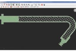
Step J: Open, orient and slice the last STL file and then apply the desired toolpaths by using Custom Groups (Figures 10 and 11).

Figure 10

Figure 11
Step K: Save the job and keep it open.
Step L: Click Combine slice curve files located in the Slice dropdown menu and import the sub-regions into the job.
Step M: Position sub-regions within the job by entering the Slice curve location (0, 0, 0). The reference feature will ensure all regions are aligned properly (Figure 12).

Figure 12
Step N: Select and delete the curves for all of the reference features by using the Delete operation located in the edit drop-down menu (Figure 13).

Step O: Save the job.
Step P: Creating Variable Density Parts procedure complete.
