

Variable Density FDM parts with Advanced FDM in GrabCAD Print

A tutorial on how to create an FDM part with discrete zones with different infill patterns & densities. This is a great but simple tactic for reducing the print time and cost of your designs as well as making them both stiff and lightweight.
-
Step 1: Introduction
How do you print a part like this? Fully dense on the outside, sparse on the inside, and with some 'extra meat’' around the joint?

Or what about like this other example? A low density infill at one end and a higher density at the other?

Keep reading and you'll see how...
-
Step 2: Why?
So what are we doing here?
Well, we want to find a way to define discrete zones in our model and give each zone different toolpath properties in our CAM software for additive manufacturing- GrabCAD Print. For example, varying the amount or type of infill in each area.
Why might this be useful?
Stress in a part is rarely uniform. For example, let’s take parts that are quite similar to say a cantilevered beam, where the stress reduces drastically from one end to another. Arm rests, simple brackets, handle bars, or even hooks are all good examples.

(left)https://www.3dprintingmedia.network/stratasys-angel-trains-3d-printed-parts-british-trains/
(right) https://picryl.com/media/wall-bracket-2d2bc7 CC0
Remember the second moment of area from your studies? It enables us to calculate which areas of our design will contribute to the part’s stiffness and therefore carry our load.

CC BY-SA 4.0 - IngenieroLoco https://en.wikipedia.org/wiki/Second_moment_of_area
Or if you’re not so into the mathematics of mechanics you can certainly appreciate why we use tubes and beams in our everyday lives. Not just because they’re easy to manufacture and work with, but also because they are an efficient use of material, giving us structures with high strength & stiffness to weight ratios. To get a high second moment of area for low mass, we prioritise material at the outside of the section away from the neutral axis, not in the middle.

https://commons.wikimedia.org/wiki/File:CNX_UPhysics_12_03_I-beam.jpg, OpenStax University Physics
Simply: Put the material where you need it and you will save on printing time and money!
-
Step 3: CAD Work
Theoretically, the highest strength to weight ratio structure would be obtained through topology optimization, you either need material there or you don’t.
But often these organic root-like structures aren’t exactly practical for the end application, so we come back a step to using variable density infill. Much like those tubes above, a solid shell for load carrying with the benefit of a sparse lightweight infill core prevents buckling and enables the design to be self-supporting, so we don’t need any support material.
If we want to achieve something like the image below, how do we go about it?

How?
It all starts in CAD. The workflow is actually very easy. We just need to define our regions of interest in CAD, then export the whole lot as an assembly or multibody part.
In this case our tutorial part is a pair of prototype downhill mountain bike handlebars. On a side note you might think it is a wild idea to try and 3D print a pair of mountain bike handlebars. Don’t worry- this just a draft design for a core that we’re planning to wrap with carbon fiber later on, but that’s a project for another time!

In this case, I’m experimenting with some cone-shaped faces to give me a nicely tapered joint between my different infill zones. But you could just draw each body separately in CAD. Essentially, you can use any CAD method you like that gets you two disjointed bodies in the same file.

Red: Cutting surfaces. Transparent: Part ready to be cut into separate bodies

Transparent: First solid body to be used as a solid shell. Blue: Second solid body that represents a core to have sparse infill
-
Step 4: CAM Work - Advanced FDM in GrabCAD Print
First, make sure that you’ve got the “Advanced FDM module” enabled.

Then, start a new Advanced FDM project and open your native CAD file containing the different bodies. You can use either an assembly or a multibody part.

We need to tell GrabCAD which bodies in our part we actually want to print, so we right click on the file and press ‘merge’ to put them into a group. This feature is here so if you’ve got fasteners or other parts in your assembly you can tell GrabCAD to ignore them.

Then you can set the print settings & part orientation. Obviously we need to do this at a global level as all bodies will need to have the same model material, tip size, layer height, etc.


Setting Custom Infill
Now the fun bit-click on a body, then use the right-hand menu to give it your desired properties.


Slice Preview Results

-
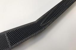
Step 5: Final Results
What does our printed part look like? I ran the .cmb file on one of our Fortus 380 Carbon Fiber edition systems and paused the print half way through the part so we could get a better look at the internal structure.


