

How to Create Variable Density Parts

FDM technology enables you to print a part with variable densities. Following the best practices can save you time and money when building your part with variable densities.
The following is brought to you by Stratasys.
-
Step 1: Introduction
A unique characteristic of FDM technology is that a single part can have regions with different build styles, which can be used to make a part with variable densities. Unlike default interior styles, such as solid or sparse that are applied to the entire part, variable densities allow a single part to have combinations of solid and sparse fill styles, and each region’s density can be adjusted independently (Figures 1 and 2).


With just a few minutes of extra design and pre-processing, you can save hours of build time and/or dramatically improve the part’s properties.
The advantages of variable density parts are:
• Optimized strength, weight, and performance
• Reduced build time and cost
• Enable niche applications (e.g., end-use parts, fiber molding, and thermoforming)
Variable density parts are created using a combination of 3D computer-aided design (CAD) and Insight software. For complete control over each region, the 3D CAD model is split into sub-components and each may have a unique density. Each subcomponent is processed with different toolpath options (Figures 3 and 4).


The use of variable density is common when optimizing a design for functionality. For example, solid fill is used where additional strength is needed, while the remainder of the part is built using sparse fill.
What you will need:
• 3D Computer-Aided Design (CAD) Software
• Insight software (documented with Insight 9.0)
-
Step 2: Modify your CAD Model
Open the CAD model to be produced with variable densities (Figure 5).

Add a reference feature (square extrusion) at the origin making it slightly taller than the part. This will assist with alignment of the various regions within the Insight software (Figure 6). Save.

Extract a sub-region along with the reference feature from the complete CAD model (Figure 7), and then delete the balance of the model (Figure 8).


Offset surfaces that mate with the main structure, giving a clearance of 0.03 mm (0.001 in). Export this file as an STL. Reopen the original CAD file and extract the next region. As with the first, retain the reference feature while deleting the balance of the model.
Repeat the above steps until all desired regions are created.
-
Step 3: Process regions using Insight Software
Configure the modeler. Open and orient the STL, confirming that the reference feature is located at the origin. Create part curves using the current parameters. From the Toolpaths menu, select Custom groups. Click NEW to create a new custom group and adjust the parameters to achieve the desired characteristics for the region. For example, change the part interior style to Sparse- double dense through Custom Groups (Figure 9).

Click the green checkmark to confirm your selection. Select the desired curves using your cursor and click ADD. All curves that are added to this group will have the toolpath parameters you defined. Save the job. Repeat the above steps for all but the last region.
Open, orient and slice the last STL file and then apply the desired toolpaths by using Custom Groups (Figures 10 and 11). Save the job and keep it open. Click Combine slice curve files located in the Slice drop-down menu and import the sub-regions into the job.


Position sub-regions within the job by entering the Slice curve location (0, 0, 0). The reference feature will ensure all regions are aligned properly (Figure 12).

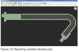
Select and delete the curves for all of the reference features by using the Delete operation located in the edit drop-down menu (Figure 13). Save your work.

-
Step 4: Conclusion
By following the best practices, you can create a part with varying densities and save hours of build time or time trying to improve your part’s properties.
