

How to FDM Print for Part Sliding Clearance

If you are 3D printing parts that have to fit/slide together after printing, you will need to put some sort of clearance between those parts in your CAD system.
A good starting place is a clearance 2x the layer height you are going to print at, but you should make a few smaller test prints at different clearances to see if the 2x layer height rule holds for your particular situation and orientation.
Have fun and happy printing!
-
Step 1:
Step 1: Figure out your Z Layer Height. You probably know by now that most FDM printers lay out beads of molten plastic in an XY plane, then move the build platform or the head in the Z direction and start again with another XY layer.
What you may NOT know is that the beads are not the same wide as they are high (which is why they are ovals in the picture above, not circles). But there IS a relation between the height and the width, and the height is usually easier to figure out in most FDM systems.
If you’re using GrabCAD Print, this is easy to find. Choose your printer in the bottom right, and then hit your “Print Settings” panel to see your slice heights. In the picture below, I’ve highlighted that I’ve chosen one of our Boston area F370’s, and that it gives me four possible slice heights (0.005, 0.007, 0.010 or 0.013 inches).
The point here is to choose ONE of those slice heights and continue.

-
Step 2:
Step 2: Convert that Z Layer Height into an XY bead width. This can either be the hardest or easiest step.
Now, typically, (let the record show that I said ‘typically’, AND stressed it), for Stratasys printers, your XY width was 2 times your Z height, because the nozzle squished down the bead, to make it stick to the previous layers.
So, if I chose a Z height of 0.005” to print at, my typical (let the record show…) XY layer thickness would be 0.010 inches. Thus, when designing my sliding components in CAD, I would start by leaving 0.010” clearance between those moving parts.
Of course, many printers have different values for this conversion (typically…) so make sure to check this for your own system. But 2x the Z height is a decent place to start.

-
Step 3:
Step 3: Test the fit with a small, 35-minute print, BEFORE making your HUGE, 27-hour print.
3D printing is supposed to be all about the testing and iterating, right? So we’d be foolish not to iterate and test on this key idea too before printing your masterpiece of sliding motion. -
Step 4:
So, here is me, trying to fit a base and cover together with NO gap between the parts in my CAD
Unsurprisingly, they don’t fit.

-
Step 5:
Now here’s me, putting together a base and cover with 0.010” gap in my CAD files.
And with 2x the Z height gap, the parts fit great!

-
Step 6:
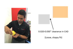
And just for one last sanity check, if I printed these parts at 0.020” or 0.030” clearance, they fit, but the fit is loose and sloppy.
If you look closely at the picture, you can even SEE the gap between the parts, which is too much.

