

Inventor / Top-down design method / Screw jack

This is the second installment of real design examples using the top-down design method.
This time we will show an example of a screw jack design.
-
Step 1: Goal
If your design requires checking for movement, you will need a non-fixed constraint. I would like to show that even in such cases, a method of proceeding with design based on the concept of Tope-down is effective.


The dataset is uploaded below, so please use it as a reference.
https://grabcad.com/library/scissor-jack-21/details?folder_id=11828956
-
Step 2: Skeleton
Reference materials
This time, as a reference material, I used the design of a pantograph-type screw-type jack from the ``Specialized Basic Library: Mechanical Design and Drawing Learned by Examples'' by the Toyohashi University of Technology College of Technology Education Collaboration Project (author).

Details such as determining specifications and calculating strength will not be introduced here, so if you are interested, please refer to this book. I highly recommend it as it is very detailed.
skeleton
For the basic specifications, we take the dimensions from the book as they are and create a skeleton. This time, since it is something that moves like a pantograph, I also created a sketch of the skeleton so that you can check the movement.

The structure of the pantograph is designed to ensure the width of the part that receives the load, and to ensure that the loading platform remains horizontal even when the jack moves up and down. In reality, the gear shapes are squeezed together to prevent rotation, but at the sketch stage, they are made horizontal using geometric constraints.
In addition to the part showing the actual posture of the arm, a horizontal sketch has been created. This is because it is easier to work in a horizontal state when modeling parts using a skeleton.
Create a sketch of the right side based on the end of the lead screw. The reference position is geometrically projected from the front sketch.


Check operation with sketch drive
If you change the parameter called jack height, the pantograph will move up and down. If you change this parameter continuously, you can check the movement of the pantograph.
The dataset is uploaded below, so please use it as a reference.
https://grabcad.com/library/scissor-jack-21/details?folder_id=11828956
The skeleton file name is 3371 ねじ式ジャッキ skeleton.ipt
Look for a file named skeleton.
An error occurs when the iLogic form in the skeleton file is executed.
Therefore, please modify the slider setting for the jack height parameter as shown in the screen below.


-
Step 3: LOD200 Multi Solids

LOD200 conceptual design model
Use skeletons to create conceptual design models of major parts. We will use multiple identical parts, but only one of them will be created here. Also. Create on the part model. Each part will be a multi-solid part model created with solids.
Although there are differences from the completed model, it is good to use this model as long as you can see the image of the completed model and the connections between the parts.
Pay attention to the arm. It is modeled in a horizontal position. The arm is a moving part that follows the vertical movement of the jack. Later, we will use joints to constrain it. Therefore, it is made horizontal to make modeling easier.
Create the main parts as multi-solids. Detailed design derives this solid model.

-
Step 4: LOD300 main parts arrangement

Detailed modeling of parts
Arrange the parts that will serve as the reference for the jack's movement. Lower bed, base. Upper loading platform, loading platform. Threaded rod and hinge. Create a detailed geometric model of each part.
Place main parts
Place those parts by fixing them to the origin.


Upper loading platform, loading platform. The positions of the threaded rod and hinge will change depending on the height of the jack in the finished product, but initially they are fixed at the origin. If the position is free, parts may move to unexpected positions when assembly constraints are set. To avoid this, fix it first.
-
Step 5: LOD300 arm subassembly

Arm subassembly
The arm part has two arms connected via a stay. These three parts move as a unit, so they are considered a subassembly.
Create the arm and stay parts by deriving from the LOD200 skeleton. Place this on your subassembly. Place the arm and stay fixed at the origin. Place another arm "without fixing it to the origin" and constrain the assembly.

Mate restraint with the side of the stay and the side of the arm

Mate constraint at the center axis of the hinge hole
upper arm
Follow the same steps to create the upper arm subassembly.

The only difference between the upper arm subassembly and the lower arm subassembly is the shape of the stay. A relief is provided to prevent the stays from interfering with each other when the jack is folded. So, create the subassembly using exactly the same procedure except for preparing the stay separately. (Since the width of the stay is shorter than the lower side, both arms are restrained as an assembly.)
-
Step 6: LOD300 Slider joint on loading platform

Movement of loading platform
The loading platform moves up and down in accordance with the feed of the jack screw. One way to give movement is to use assembly constraints, but we will use joints, which are easier. The joint has the same function as the joint provided in Fusion360.
Show only selection
Display only the necessary components for easy operation.

Remove the fixing restraint of the loading platform.
Select only two components, the base and the receiving bed, and execute Show Selection Only from the context menu.

Show skeleton sketch
From the browser, expand each component to display the skeleton sketch (front SK) inside the derived component.

Set the slider joint
Set the joints using the edges of the skeleton sketch. Name the joint "Location position".


Fixed and restrained loading platform at origin
Return the loading platform to the origin and to the fixed restraint state. I will be attaching the arm to the loading platform later, and I want to make it easier to attach it at that time.
To constrain it to the origin, set all XYZ coordinates of the occurrence to zero. It takes a lot of time to do it manually, so I create a rule in iLogic that fixes it to the origin and use it.
I made a video of the series of operations.
-
Step 7: LOD300 Rotating joint on arm

Place arm
Place the arm that was made into a subassembly. The method is the same as last time. Place the arm and display the front sketch of the skeleton from the base and arm browser.

Add rotation joint
Add revolute joints using the skeleton sketch.


Follow the same steps to set up the upper arm as a loading platform and rotation joint.
Mate Constrain of arms
Add mate constarain two arms. Since there is only one degree of freedom left and it is easy to operate, we use a mate constraint for axis alignment.

Check movement
Remove the fixed restraints on the loading platform and check the movement.

movie
I made a video of the series of operations.
-
Step 8: LOD300 threaded rod installation

Attach the hinge to the arm and then attach the threaded rod.
Attach the other side of the arm assembly using the steps outlined last time.

hinge
Attach the hinge that is the joint of the arm. First, flash restraint with base and front WP.

Next, mate the arms and shafts.

Constrain the opposite hinge (with screws) in the same way.

The hinge shafts (for threaded rods) are mate-constrained.

Installing the threaded rod
Attach the threaded rod to the hinge with a rotating joint.
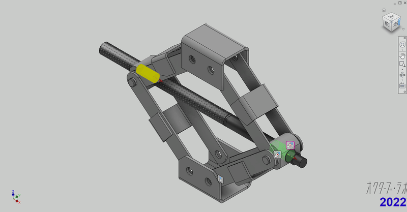
Attention, joints are useful, but you need to be careful in choosing your geometry. This is because geometry may disappear as a result of editing the model. (For example, if you have deleted a chamfer feature.)
It may be better to take the extra effort and use an axis-to-face mate constraint.
Movie
Click here for a video of the series of operations.
-
Step 9: LOD300 base/load receiving plate installation

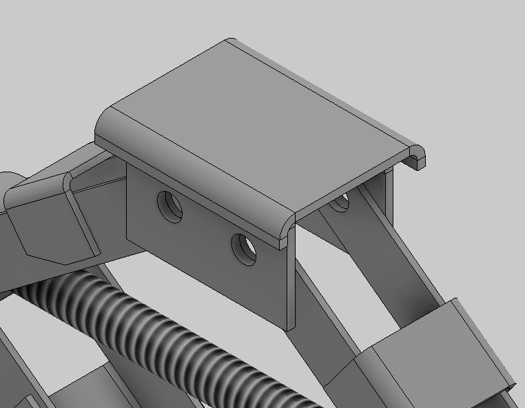
Installing the base and receiving plate
This section explains how to install the base and load receiving plate.
The base is in a fixed position regardless of the movement of the jack, so it is "fixed to the origin". On the other hand, the loading plate moves with the loading platform, so it is fixed against the loading platform.

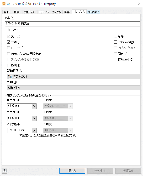
When making drawings, the jack must be in a fixed position. I call this as original position. In the case of a loading platform, you can simply constrain it to the origin, but since it has already been placed, you cannot use the component placement menu.
To place a component at the origin, all coordinates (x, y, z) of the placement position should be set to zero. You can specify it from the occurrence tab of the property, but it is a bit troublesome.
Fixing the receiving plate to the receiving platform
The loading plate is fixed to the loading platform. Since these two parts are derived from the same skeleton, they can be fixed by flush constraining the basic work planes.
Movie
Attention
In this video, I used some rules that help add constrains. If you are interested in the rules and would like to try them out, please contact me.
-
Step 10: LOD300 Bolted Connection Generator

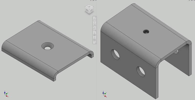
Secure the loading platform and loading plate with bolts. The flange of the receiving plate is prevented from rotating, so only bolt it in one place in the center.
bolted connection generator
Use a bolted connection generator. The bolt connection generator is an excellent product that not only inserts bolts but also creates holes (screw holes) at the same time.
On point, option
My favorite method is specifying points. This is because it requires the least amount of work, as it is sufficient to specify the hole position using sketch points at the skeleton stage.
Temporarily display the receiver plate sketch from your browser.

Start the bolt connection generator and place the bolt on this point.
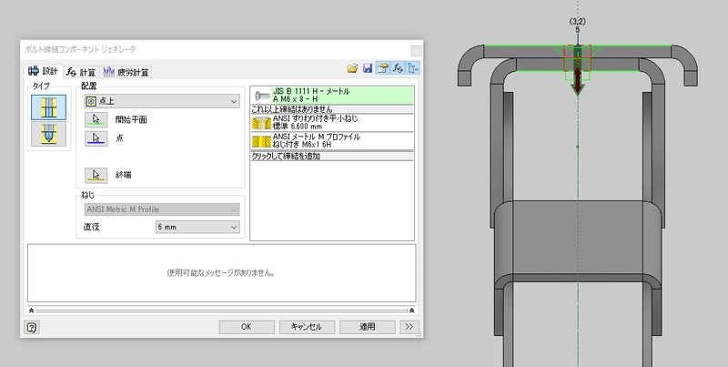
Hide the sketch and complete the installation.
Hole features are automatically added to the receiving plate and receiving platform parts.
Click here for instructions
