

Inventor / Top-down design / Drive unit (Chapter 1)


Inventor's top-down design introductory material. The design procedure from conception to detailed design is introduced using the drive unit as an example.
Chapter 1 describes from the creation of the skeleton model (LOD100) to the conceptual design model (LOD200).
-
Step 1: Intorduction
I needed a realistic design example to explain the top-down design method, so I actually tried the design. I would like to introduce the procedure.
Goal
The goal is to complete the 3D model and drawings (assembly drawings / parts drawings) as shown below.


The original design is a unit called "Horizontal Auger filling" in the GrabCAD library.
Only the drive part is taken out.
The author of the original model has already agreed to the redesign.
Designed from scratch based on JIS, assuming that it will be manufactured in Japan. Therefore, the shape and dimensions are different from the original.
I have more than 10 years of work experience in design, which is more than 25 years ago. I don't think I'm doing anything strange, but I'd love to hear any advice.
First of all, create a LOD100 level skeleton part.
A detailed explanation will be given in the next step.
-
Step 2: LOD100 Skeleton
Step 2 describes the LOD100 phase skeleton.
LOD is Level Of Developement, which is a concept that rules the content of deliverables and the level of detail of models for each development progress.
LOD100 is the design phase of planning and conceptual design.
Skeleton (LOD100)
Describes a conceptual design (LOD100) level skeleton.
At this stage, the specified dimensions have not been finalized. The first step is to make it into a shape.I will create a sketch with approximate dimensions.
You may not be familiar with the name skeleton. A skeleton is the equivalent of a draft line / auxiliary line in a handwritten drawing or 2D CAD drawing.
Here, the sketch is created roughly. I will not write the detailed shape. Some people write more and more shapes in the sketch from the beginning, but I try to keep only the basic shapes.
As a result of various trials and errors, it was found that it is easier to design by separating the skeleton (LOD100), which is mainly based on the specified dimensions, and the skeleton (LOD200), which has related dimensions and shapes.
So I am doing this.
Define the position of the base

Based on the driven axis of the timing belt, the X-axis and Z-axis are defined as shown in the figure, and the neutral plane of the timing belt is the XZ plane.
Which should be the origin and which direction should be the X direction depends on the designer's way of thinking.
I have decided that the Z axis is upward and the orientation of the main projection is the XZ plane.
In the case of this example, the origin can be any of the drive shaft, output shaft, and surface plate. Here, I decided on the output axis (driven axis)
First sketch
The first sketch is created in the orientation of the main projection (front view) in the mechanical drawing. It is the direction seen from the front of the figure. The problem here is that in this orientation, you are looking at the back of the XZ plane. If you create a sketch on the XZ plane as it is, you will be writing the sketch from the back side. This is not interesting.
Therefore, I create a work plane so that the front side is facing up. Specifically, it is parallel to the XZ plane, has a zero offset length, and has the normal direction reversed. I have prepared a parts template with this work plane (FRONT_WP) prepared in advance.

On the browser, select FRONT_WP to start 2D sketching. Then, a sketch with the front side will be created. Name it FRONT_SK.

The figure above shows the state where the sketch has been drawn.
The important thing is ...
- Give key dimensions a descriptive name
- Create with construction line
- Completely constraint
The name (parameter name) given to the main dimension should not be a symbol such as A, B, C, but a name that also serves as an easy-to-understand explanation.
You can reduce the risk of misunderstanding when referring to it later. It is easy for other people to see.
Here, the axes are named A-axis, B-axis, and C-axis, and the parameter names are named by referring to these.
At this stage, we do not create extrusion features or rotation features. So, there is no problem even if it is a construction line. I make it a construction line because this sketch treats it as a draft line / auxiliary line.
You can create a model without being completely constrained, but it will cause an error when you edit it later. For example, 'the profile cannot be found'. (It was closed at first, but it opened after editing)
Axial cross section sketch
Next, make a sketch of the cross section of each axis.
- 1. Create work axes for B-axis and C-axis (A-axis is the same as Y-axis)
- 2. Create a work plane that passes through the C axis and is parallel to the YZ plane (the AB axis is the same as the YZ plane)
- 3. Create sketches for each (drive unit right SK, driven unit right SK)
Drive right SK

Drive right SK

Make a geometry projection so that the dimensions are not duplicated.
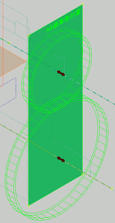
Completion of LOD100
Finally, it should look like the figure below. (Dimensions are hidden because it is difficult to see)

The parameters look like this. (Display only key parameters)

The browser looks like this.

note. The AB gear mounting surface, COVER _FRONT_SK, and COVER_R_SK will be the work planes and sketches added as needed in later designs. It will not be created at the stage of LOD100. (Because I am explaining using the completed sketch, I will also show what I will add later)
The convenience of 3D CAD is that it is very easy to change because the shape changes just by changing the parameters. It's hard to make corrections with handwritten drawings, but it's a lot of work because you have to make full use of stretching even with 2D CAD.
When completed so far, imagine the completed shape from the shape of the sketch. Then, we will verify that there are no problems or that the dimensions can be made smaller.
Based on this skeleton, we will design the LOD200.
-
Step 3: LOD200 skeleton
Describes a conceptual design (LOD200) level skeleton model.
Skeleton (LOD200)
At this stage, the specified dimensions are almost fixed. We will derive the skeleton of LOD100 and create the 3D shape of the main parts. I will not make a detailed shape. We will make the shape while watching the connection with the adjacent parts.
In handwriting and 2D design, rough isometric drawings may be handwritten, but it can be said that they are made in 3D version. However, the crucial difference is that creating a skeleton is an important part of the design workflow. The detailed design that follows is based on the LOD200 skeleton model created here.
Make multiple parts of the 3D model of the main part. Here, it is created with a part document. Use the multi-solid feature that allows each part to be created in a separate solid model.
The reason for making it a part document is that it is easy to create and manage. It is very efficient to be able to design different parts on one document. One of the reasons is that if you create a model in this way, the origin is shared between the models, so when you make an assembly, you do not need to do the work of "constraining".
Derived component
Use the features of the derived component to reference the LOD100 level skeleton. Create a new part, perform a "derivation", and capture the LOD100 level skeleton as a reference component.
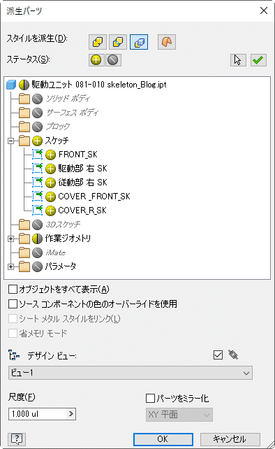
In the Derived Parts dialog box, select which object to derive. You can edit it later, so select only what you need.
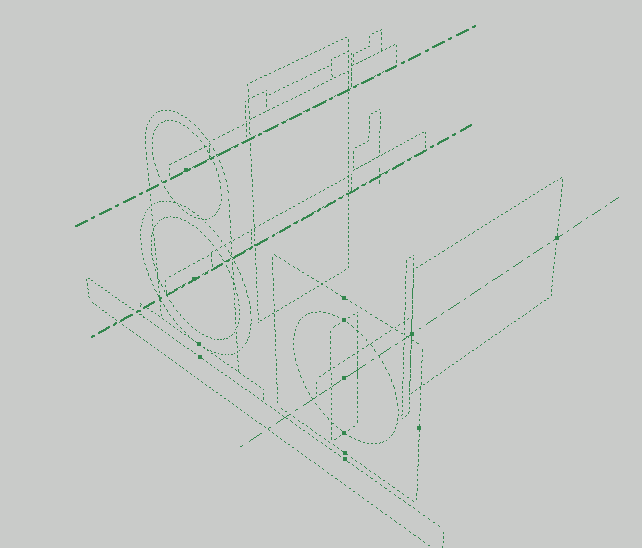
Add profile
I will add a profile. (Dimensions are hidden in this figure for clarity.)
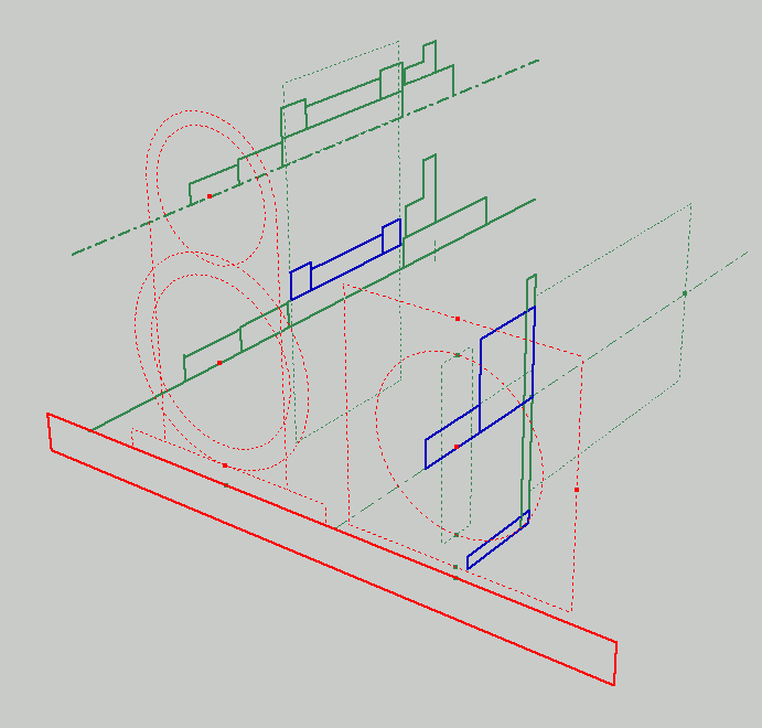
I will add a profile. (Dimensions are hidden in this figure for clarity.)
The profile is added to the derived sketch. Instead of adding them all at once, edit the sketch each time you model a part. The figure shows its final state.
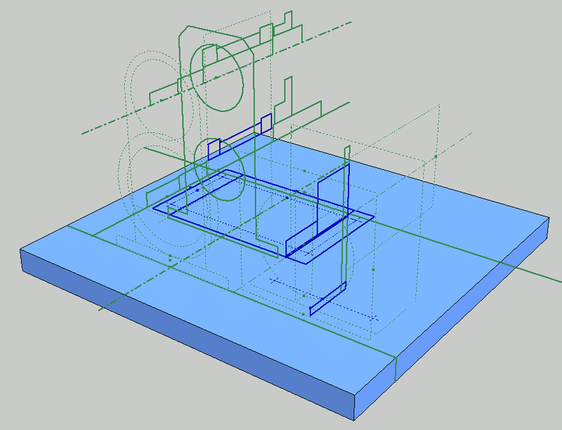
Create each part with multi-solid
Using the profile added to the sketch, a solid model is created for each part.
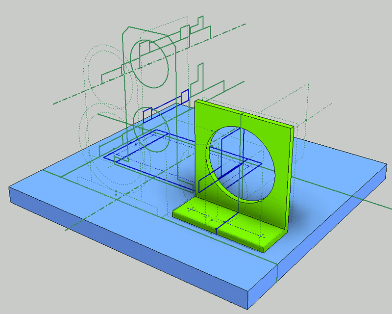
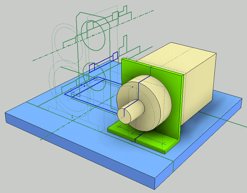
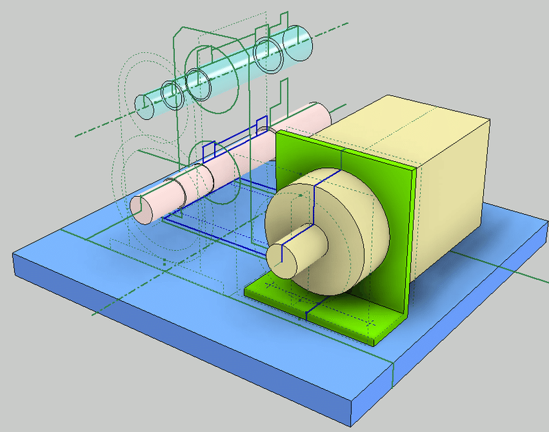
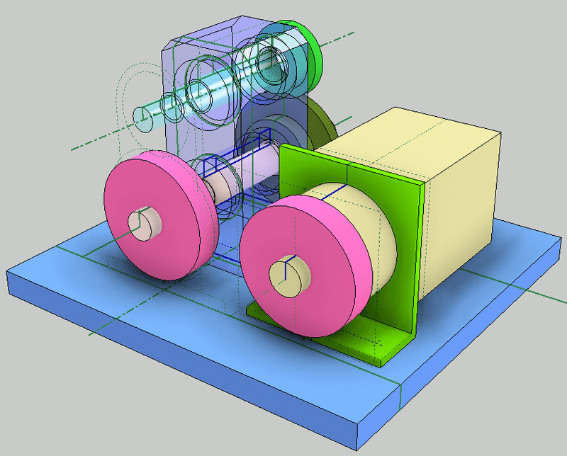
Name each part (solid).
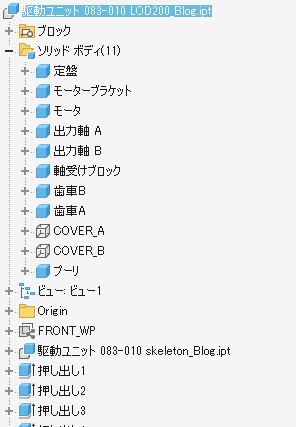
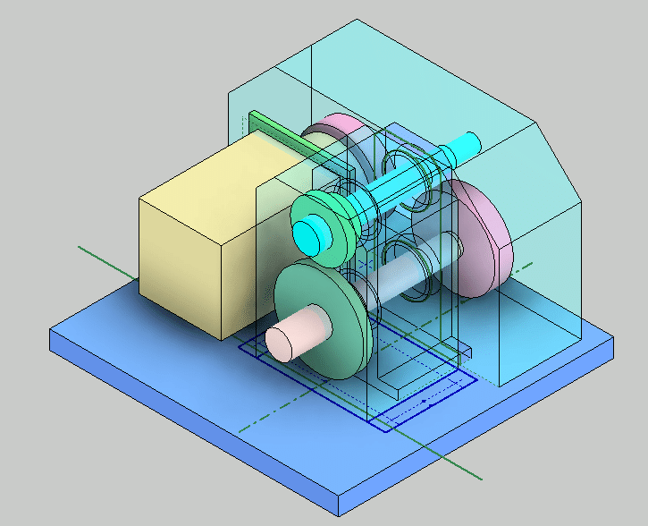
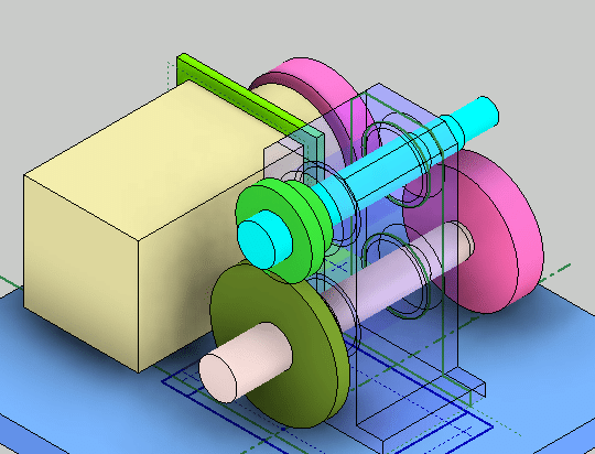
Validate 3D models from different orientations.
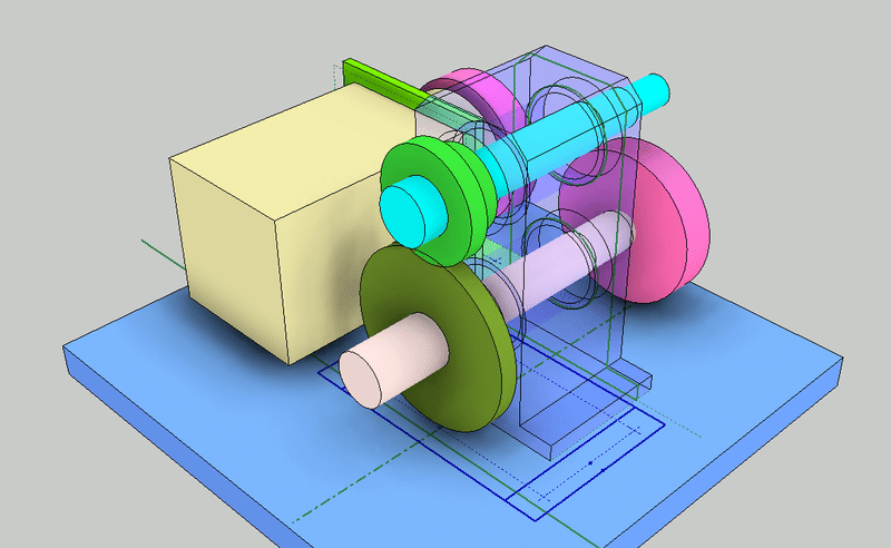
Each solid is color-coded so that the relationship between the parts can be easily understood. The bearing block has a translucent color (appearance) so that you can see the inside.
Design check
I was able to model with the level of detail of the concept design (LOD200).
Before moving on to the detailed design (LOD300), we will do a design check.
Confirm the correctness of the design by checking the shape and dimensions, the driving force of the motor, the strength of the shaft, the selection of the timing belt, the calculation of the spur gear, and so on. If there is a problem, go back to the LOD100 and LOD200 skeletons and fix the model.
-
Step 4: LOD200 Design check
Explanation of design check using 2D projection drawing of LOD200
Design check
The general configuration was completed in Step3. Before moving on to detailed design, we will do a design check. In addition to checking the shape and dimensions, we check the correctness of the design by performing motor driving force, shaft strength, timing belt selection, spur gear calculation, and so on. If there is a problem, go back to the LOD100 and LOD200 skeletons and fix the model.
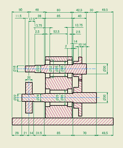
Creating a 2D projection
The first task is to create a 2D projection.
Checking the 3D model from a free perspective is good because you can intuitively understand the shape and the connection between parts, but it is troublesome to check the exact shape dimensions and internal shape.
Therefore, a 2D projection drawing is created when a certain shape is created. It is not a drawing for official publication. It is a drawing for confirmation.
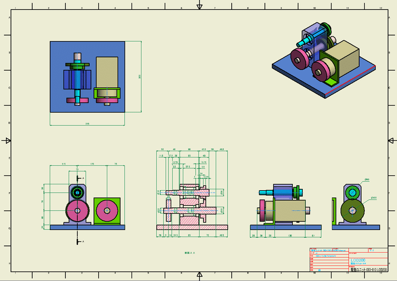
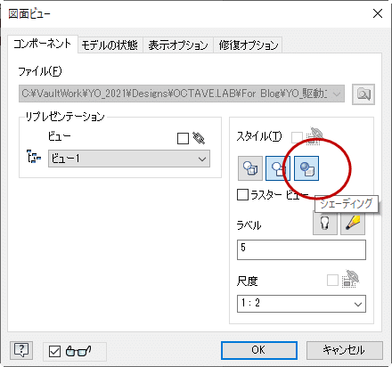
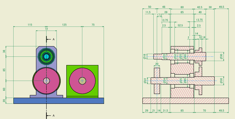
Color map parts
This drawing is not an official drawing. It is most important to be easy to understand because it is used by designers for design checks. I think it's a good idea to display the color mapping of the 3D model.
Create dimensions
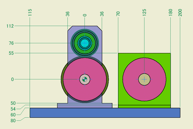
Here, we don't think much about the standard and create the dimensions between the edges of the required outline. As you gain experience in designing, you will be able to understand where and where to check the dimensions.
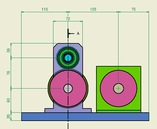
Displaying the dimensions from the reference as incremental dimensions is also a good way. If you are good at mental arithmetic, this may be better.
Cross section
Create a section view to show the inside of the machine. The good thing about 3D CAD is that you can easily create a cross section. Create a cross section where you need it and create the dimensions.
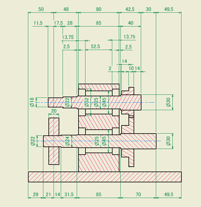
If you find a problem, go back to the LOD100 or LOD200 skeleton and edit the sketch shape and parameters. The edited result is reflected in the 2D drawing. You will check again then.
-
Step 5: LOD200 Toothed Belt Design check
The drive unit transmits torque from the servo motor to the gearbox with a toothed belt, and accelerates with gears. In this step, we use Inventor's Design Accelerator to check the design of toothed belts and gears.
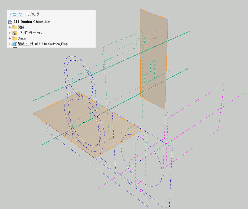
Assembly model for design check
Create a new assembly model and place the LOD100 skeleton model at the origin. Use this assembly model to check the design of toothed belts and gears.
Toothed belt and pulley
This time, we will use MISUMI's surface pressure timing pulley L type (model number MTPL30L075-E-22). Check if the structure is actually established.
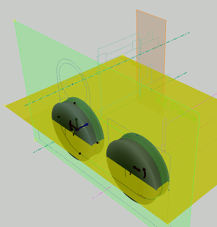
Toothed belt component generator
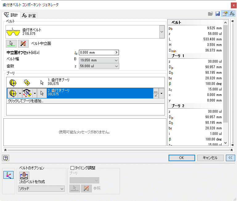
Follow the instructions in the dialog to determine the position and size of the pulley.
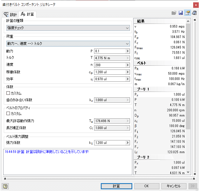
check the strength from power, speed, and torque.
If there is no problem with the calculation result, save this setting as a template. This setting will be reused when creating the detailed model of LOD300.
OK to exit the component generator.
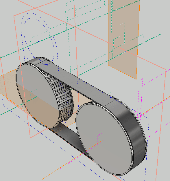
Save assembly model
Overwriting saves the components of the toothed belt. It is saved in a folder named Design Accelerator.
-
Step 6: LOD200 spur gear design check
In this step, you will check the design of the gears. The skeleton is created by deciding that the speed ratio is 1.6, the speed is increased, the module is 2, and the distance between the centers is 76. Check that there are no problems with dimensions, meshing, and strength.
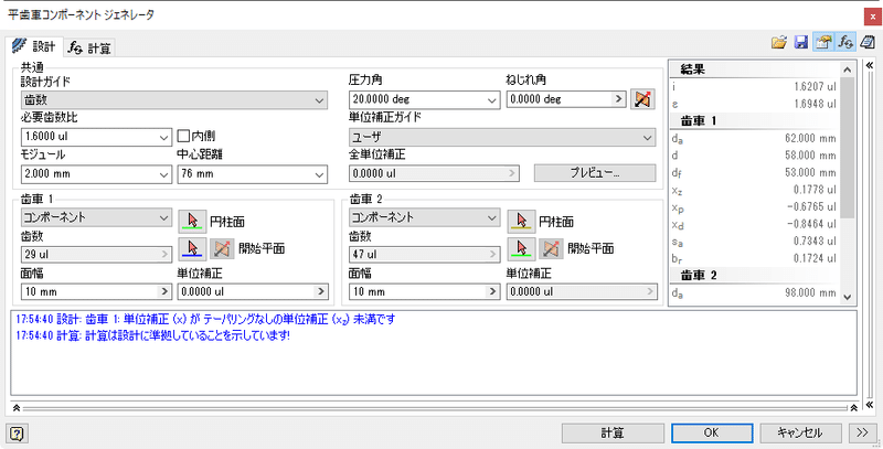
Spur gear component generator

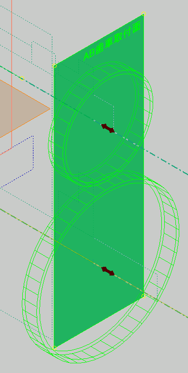
The design guide is "number of teeth". Enter the gear ratio, module, and center distance. Specify the load and material from the calculation tab. Next, select the central axis (cylindrical plane) and starting plane of gears 1 and 2 from the skeleton. Since there is no object to refer to, select the central axis, but since sketch lines are not accepted, select the work axis. You can also select from the browser.
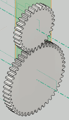
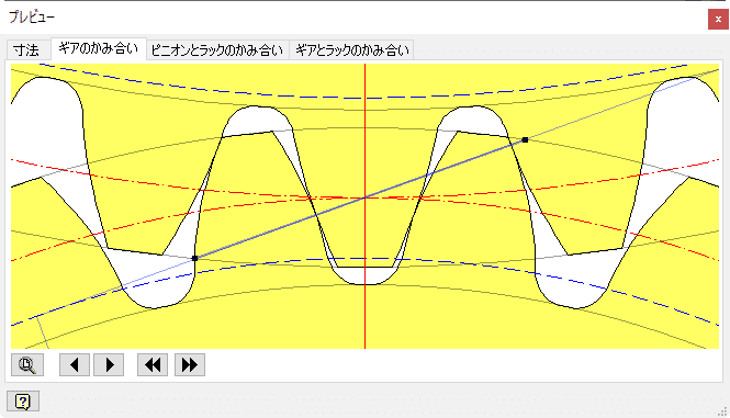
A preview of the gear appears on the center axis and the starting plane. Then press the "Calculate" button, the design will be calculated and the result will be displayed. If there is no problem, it will be displayed in blue, but if there is a problem, it will be displayed in red. The figure below is the result of intentionally inserting the wrong distance between the centers.
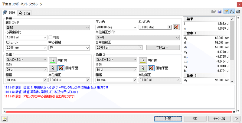
The result of entering inconsistent numbers
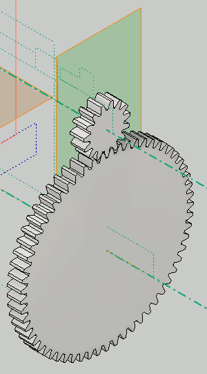
Click OK to exit the dialog box. A spur gear model is created.
You can change the design by clicking "Edit using the design accelerator". The figure below shows the result when the speed ratio is set to 4.
Restore the speed ratio and check the gear dimensions. In addition to the dimensions, you can check the tooth profile in the preview.
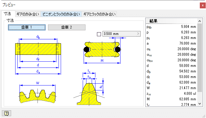
The outer diameters of the gears were calculated to be 62mm and 98mm, respectively. If it is different from the outer diameter when you created the skeleton, go back to the skeleton and correct the outer diameter. This is because the gears are created using an existing solid model during detailed design.
Save the calculation results in a file for reuse during detailed design.
Conducting design reviews
After the stage up to this point (LOD200), it is time to conduct a design review. As a result of the design review, we will make design changes. Design changes can be tedious and can hurt your pride. The good news is that design changes at this point are a lot easier than later design changes. What's more, the top-down design method is used here, so it's even easier.
As a result of the design review, we will also consider a version with the output axis spacing from 76 to 85.
Continue to the next step
-
Step 7: LOD200 Plan B
As a result of the design review, it is decided to consider a version in which the output axis spacing is changed from 76 to 85. So-called second plan, or Plan B. This is the next best thing when your favorite doesn't go well. I would like to know the background, but since I want to focus on the design method by 3D CAD in this article, I will not touch it.
Copy design
Since we have a dataset created so far, we will use this dataset to create a model for Plan B. There are various methods. Here, we will use the copy design function of Vault.
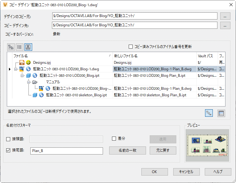
Vault Basic Copy Design Dialog Box
You can make a name-resolved copy of the referenced model at once by selecting the parent model (here, a 2D drawing in dwg format) and performing a copy design. To distinguish it from the original, we name the file name suffix Plan_B.
Modify model
Open the copy-designed model. LOD100 and LOD200 skeleton models, 2D drawings.
First, change the skeleton of LOD100. Here is the result of changing the pitch between AB axes.
FRONT_SK
Gears A and B no longer squeeze together, but let's leave them alone and see what happens to the LOD200 and the 2D drawing.
Isometric display from the back
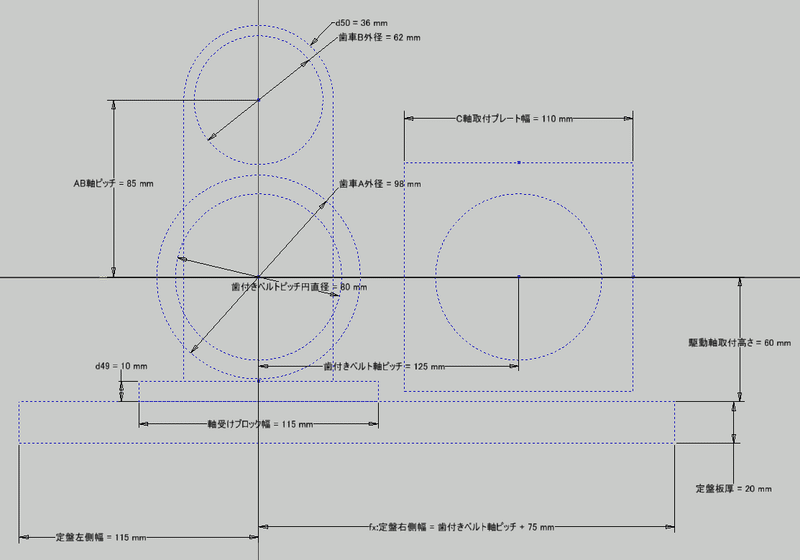
2D drawing
The shape (height) of the bearing block has changed automatically. The gears no longer squeeze together, so we know we need to make a design change.
In this way, as a result of a partial design change, there will be places where the shapes and parts do not fit together. Modify the LOD100 and LOD200 models as appropriate to modify the design. It's still in the conceptual design stage, so the modifications are easy and quick.
Gear recalculation
Open the spur gear component generator using the same procedure as for the design check.
Open the saved template. (see step 6)
Specify the position of each gear.
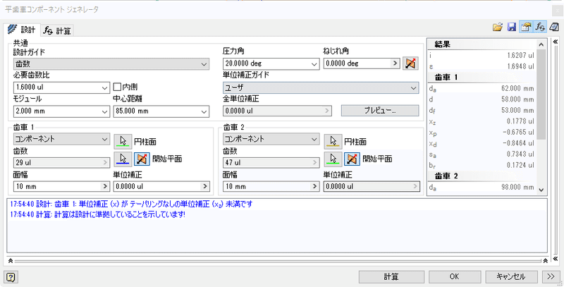
The center distance is automatically corrected to 85mm.
It is in a state where they do not squeeze together.
Now, when you execute "Calculate", the gear will be recalculated.
It came to mesh!
As a result of the recalculation, the outer diameters of the gears are 70 mm and 108 mm, respectively.
Execute OK to exit the spur gear component generator.

Correct the LOD100 skeleton with the recalculated gear outer diameter dimensions.
Completion of the second plan
Check the whole thing and solve all the problems, and you're done.
Next, let's move on to the detailed design of LOD300. Detailed design will proceed with the original first plan.
