

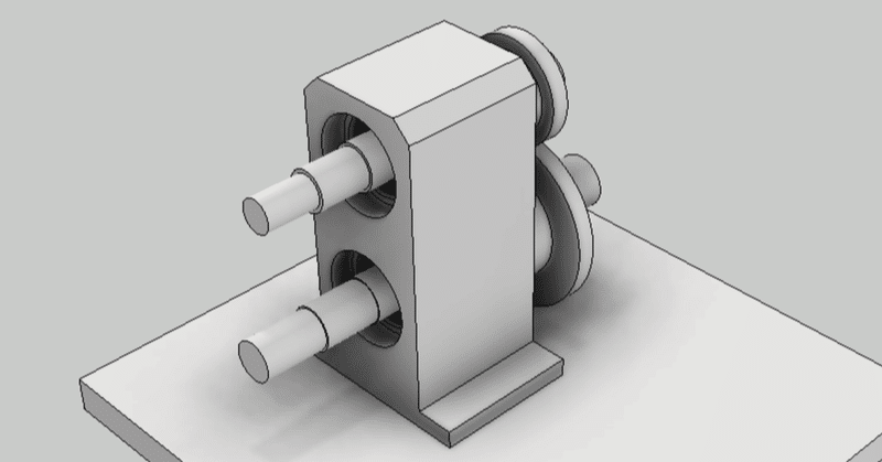
Inventor / Top-down design / Drive unit (Chapter 2)


material. The design procedure from conception to detailed design is introduced using the drive unit as an example.
Chapter 2 describes from the creation of the conceptual design model (LOD200) to the detail design (LOD300).
-
Step 1: LOD300 main parts placement
LOD300 (detailed design) phase
In the detailed design of 2D CAD, first make an assembly drawing. Next, design the parts drawing from the assembly drawing. The process of creating this parts drawing is called "disassembly". In Japanese, it is called "barashi".
In 3D CAD, an assembly model cannot be created without a parts model. Therefore, for disassembly work, we will proceed with three types of models, assembly, parts, and drawings at the same time.
By the way, there is an idea of MBD that advances the design only with the 3D model without making the 2D drawing. I agree with that idea, but I don't think the features of 3D CAD have caught up with that idea. For now, I think it's better to proceed with the design while making 2D drawings at the same time (while checking with it).
In the top-down design method, the parts model created in the LOD200 phase becomes the input (skeleton) of the LOD300. In terms of Inventor functionality, it derives from the LOD200 parts model and creates a model for each part.
Parts model creation
BASE PLATE
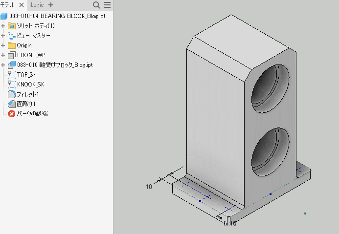
From the new part, open the LOD200 parts model using the features of the derived component.
The figure below shows the dialog box of the derived component.
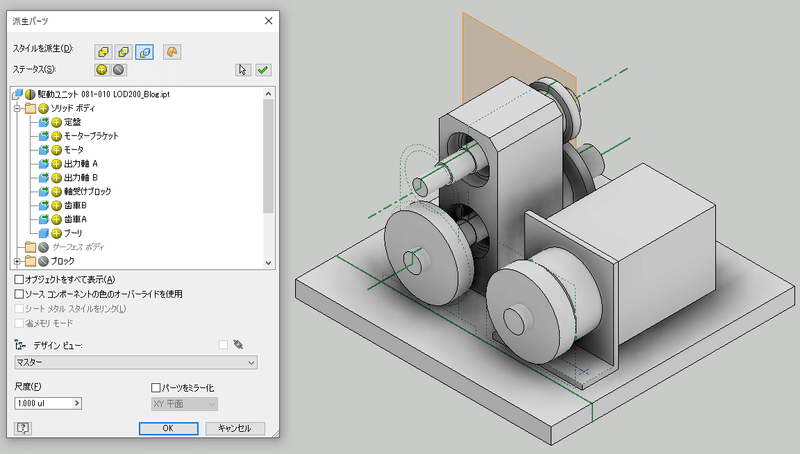
Derived only the solid model of BASE PLATE. Also, the sketches, working objects, and parameters are derived only from those related to his BASE PLATE.
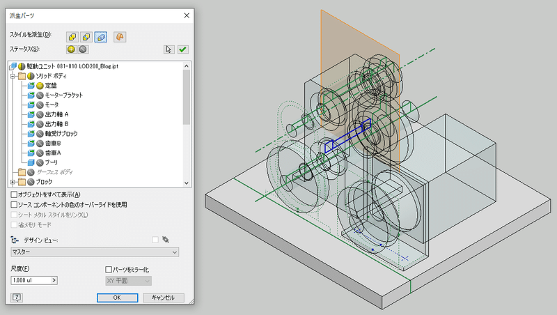
Select only objects related to BASE PLATE
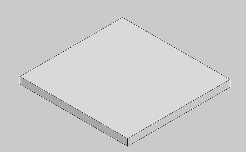
BASE PLATE parts model created (not yet completed)
Follow the same procedure to create other part models.
SHAFT(A.B)・BEARING BOX・SPUR GEAR(A.B)
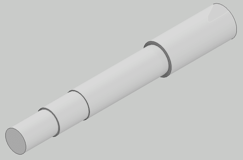
SHAFT
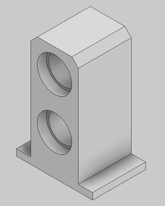
BEARING BOX
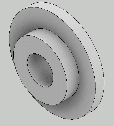
SPUR GEAR(A.B)
Assembly model creation
Place the created part model on the assembly model. Since it is based on the skeleton model, it will be automatically laid out in the correct position.
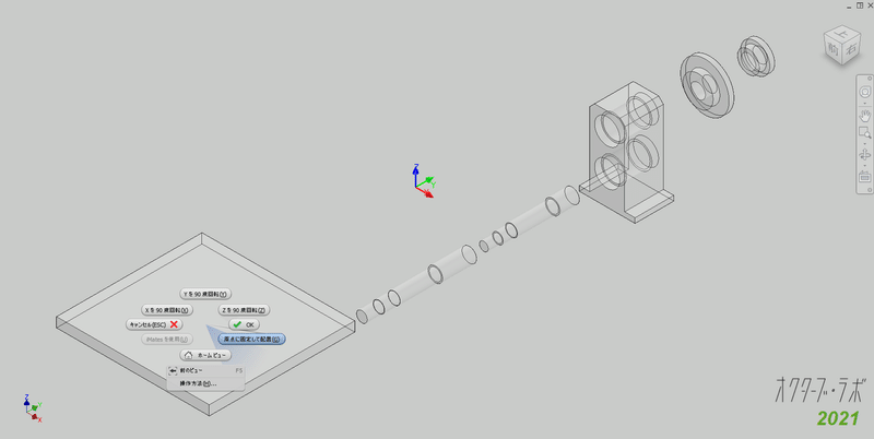
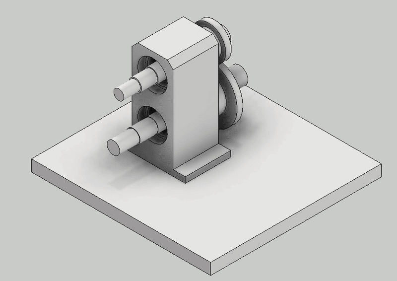
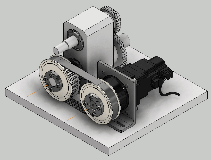
Parts are placed in the proper position
I like this technique very much because I don't have to use assembly constraints such as mate and flash.
2D drawing creation
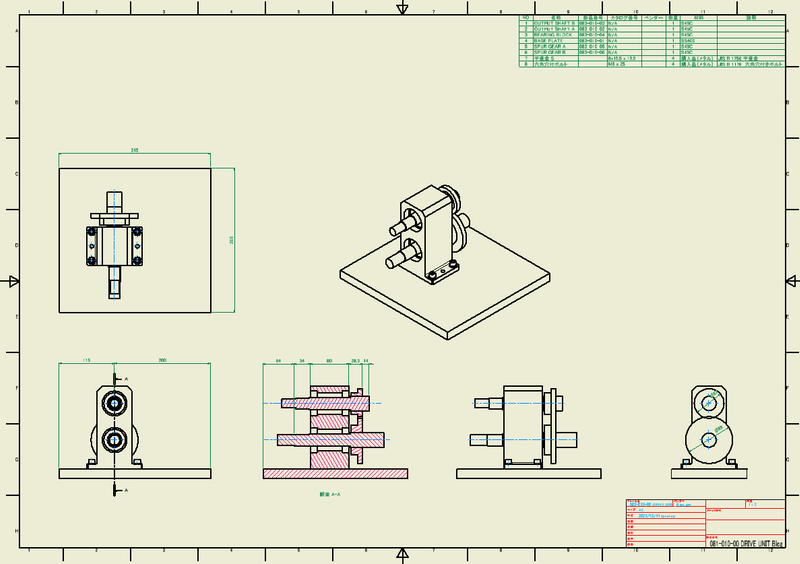
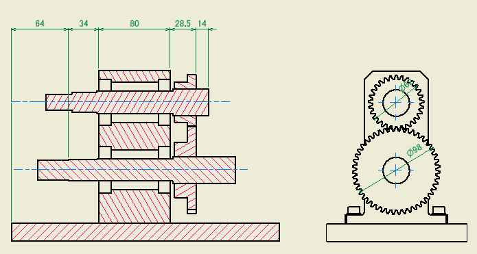
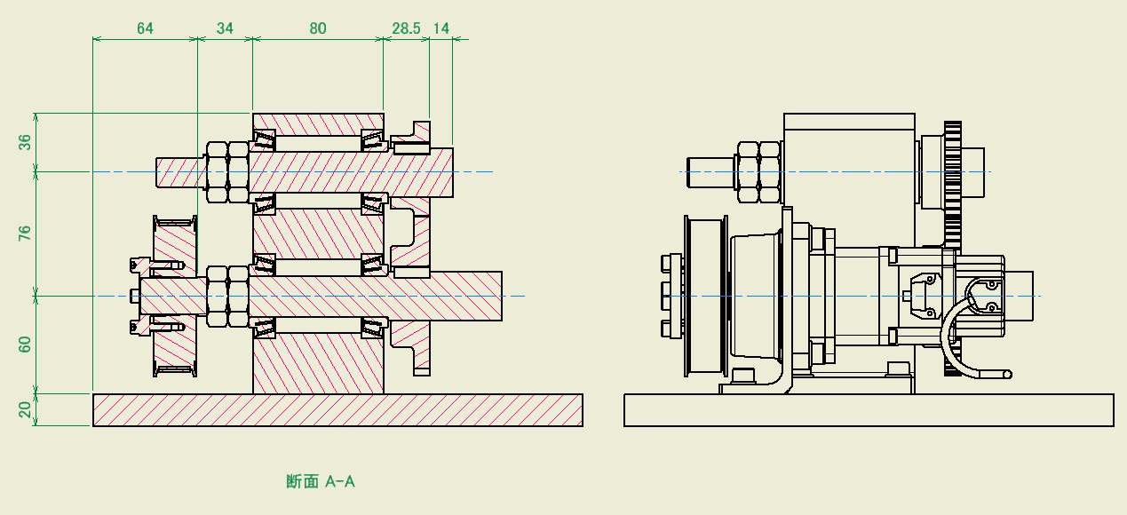
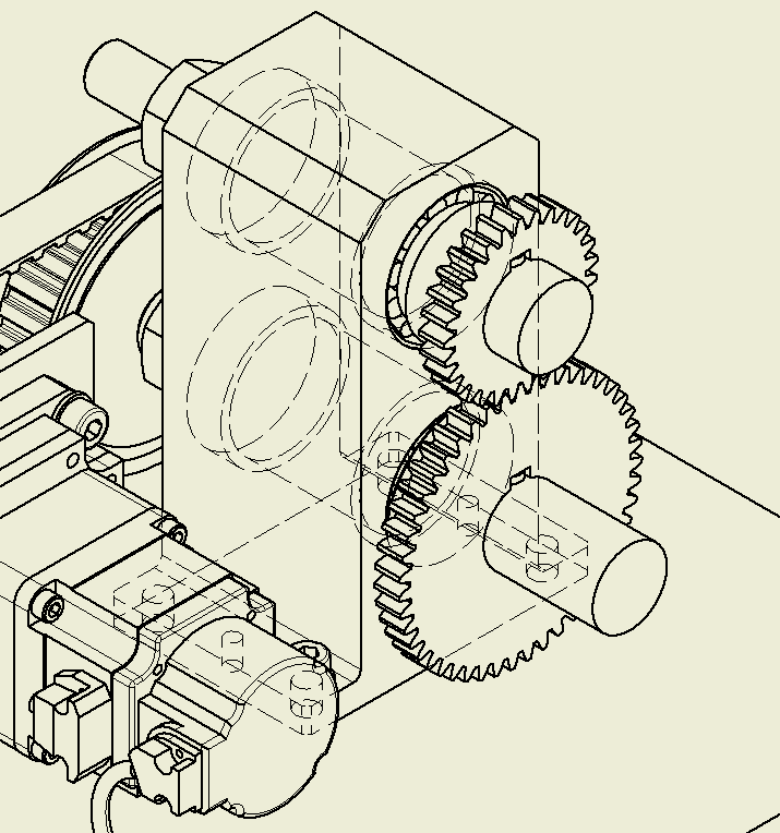
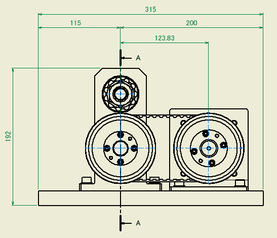
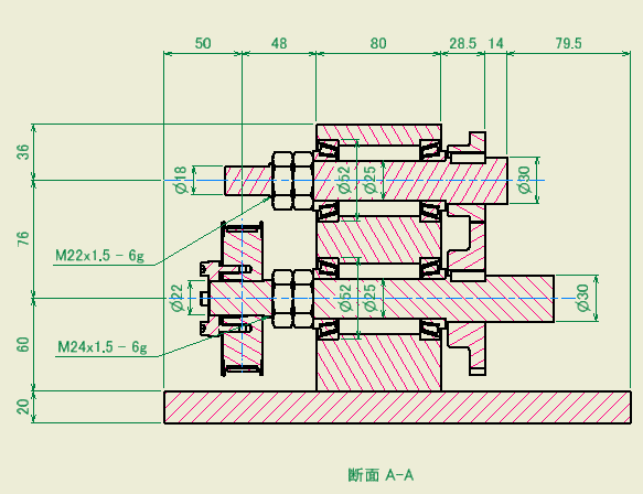
Create a 2D drawing at the same time. Create a three-view view and a cross-sectional view of the output shaft. At this stage, it should look like the figure below.
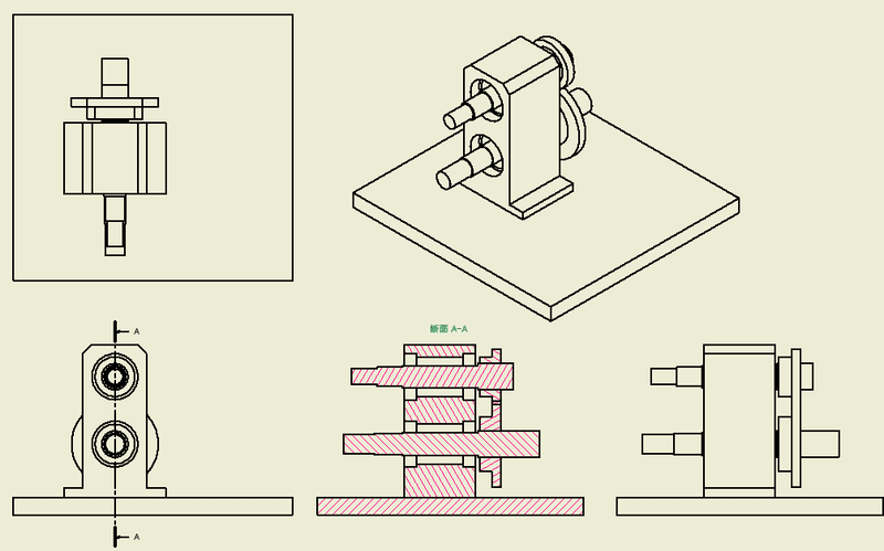
As you proceed with the detailed design, you will have parts, assemblies, and 2D drawings.
-
Step 2: LOD300 hole design
Problems in hole design
The most common mechanical design flaw is "cannot be assembled". What it means to not attach is that the parts to be assembled are in different positions, different sizes, and different types. There is also "interference" where parts collide unintentionally, but the most common is that the holes do not fit. This is because most of the parts are assembled with screws.
We will check the design to prevent any problems. In the 2D drawing, check all parts to see if there is any contradiction in the dimensions, size, and type of each other. This is a daunting task. In this respect, 3D CAD is convenient. If you use the interference check function, it will automatically identify the inconsistent parts. Although it is not possible to find 100% of the problems, it is one of the merits of using 3D CAD that the number of design defects is drastically reduced by using this function.
However, the interference check function is a function to find design defects and does not prevent the occurrence of design defects. It is very important not to cause design defects.
Design holes and fasteners at the same time
The reason why defects occur is that the holes are designed for each part. This is because the hole dimensions, size, and type are entered for each part. If related parts can be input at the same time with one input, there will be no contradiction between the parts. Inventor uses a bolt fastening generator.
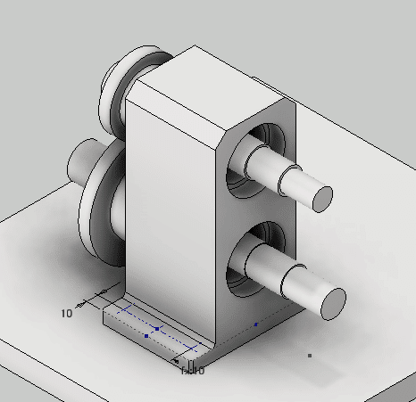
Sketch definition of hole position in bearing block
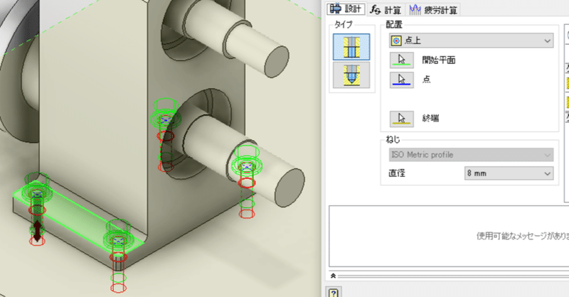
Create a sketch on the bearing block and define the location of the holes as "points". The mounting screw holes (4 places) and the positioning pin holes (2 places) are sketched separately.
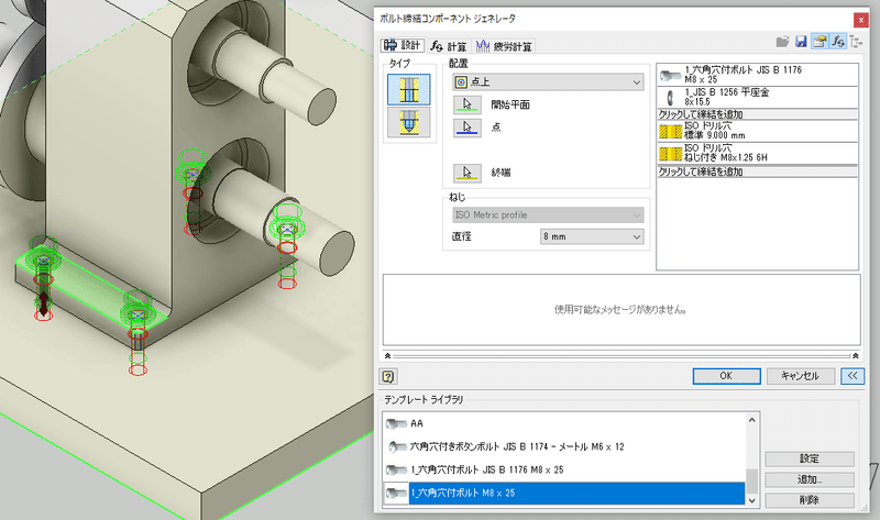
Create holes and fasteners at the same time with the bolt fastening generator
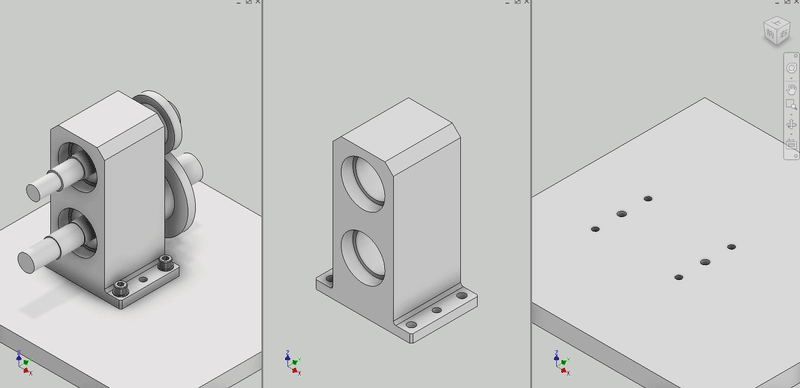
Open the assembly model.
The sketch created on the bearing block is displayed.
Run the bolt Fastening generator.
It makes holes in both the bearing block and the base plate in one operation, and also arranges bolts and washers. There are no mistakes in position, size, or type.
What about design changes?
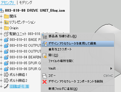
Execute "Edit using Design Accelerator".
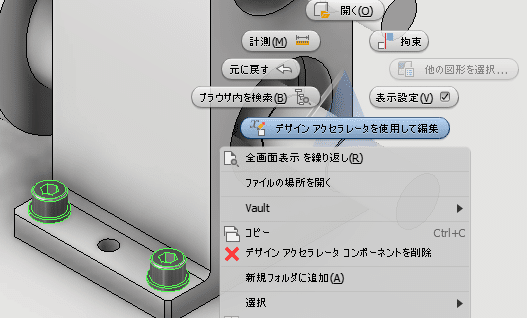
The Bolt Fastening Generator dialog box will appear, where you can modify any changes. If there is a hole position correction, correct the position in the hole sketch in advance and then run the bolt Fastening generator.
Benefits of using point options
In the placement option, you can use an existing hole, but if you select a point, the hole will be created automatically. It is easy to use because the size of the hole can be changed and the sketch can belong to any place.
Precautions when using design accelerators
If there is a change in the upper model, the lower model will be updated automatically, but the model created by the Design Accelerator will not be updated automatically. You need to use the Design Accelerator to perform the edits.
-
Step 3: LOD300 Spur Gear
Spur gear drafting
When I was drawing by hand, I didn't write a tooth profile when I wrote a drawing of a gear. Even JIS gear drafting requires only the outer diameter, pitch circle, and tooth base circle. On the contrary, if you write a tooth profile, it becomes "unnecessary meticulousness".
When it comes to 3D CAD, you can expect it to look good, so you need a model that looks like it, even if it is not an accurate involute curve. Of course, you can sketch the tooth profile yourself, extrude it, and copy it to make a model, but it is more convenient to use the gear making tool.
Spur gear component generator
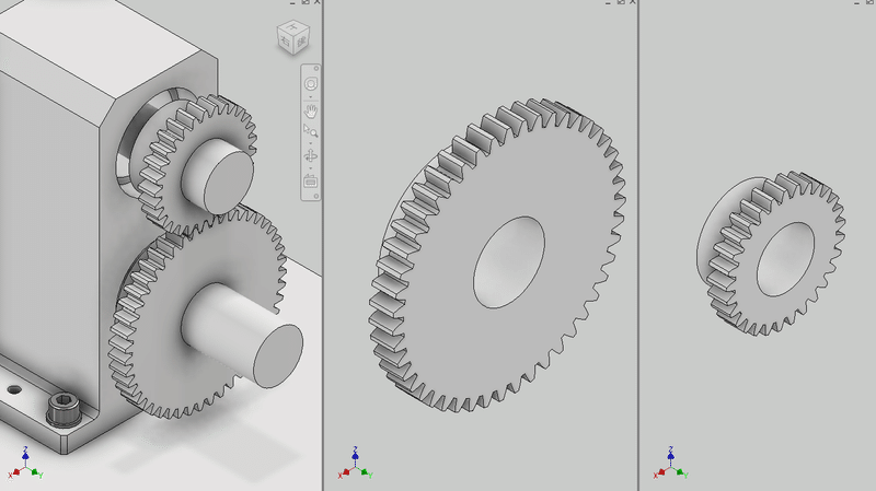
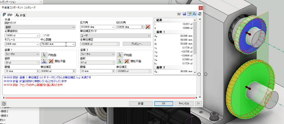
I used it for conceptual design, but I also use it for detailed design. Let's run the spur gear component generator from the assembly model.
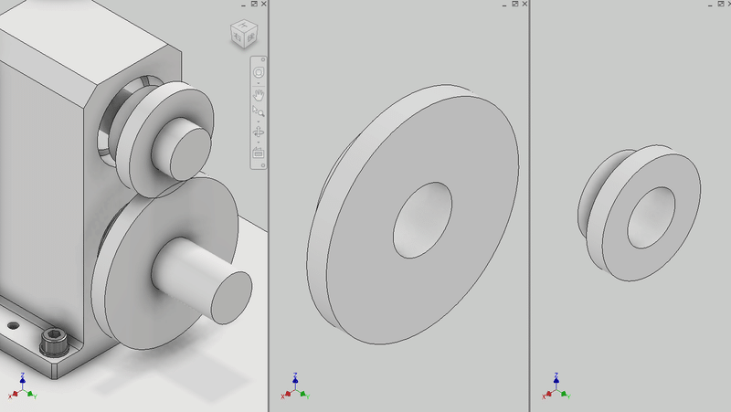
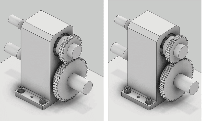
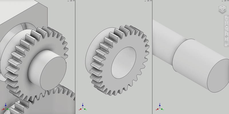
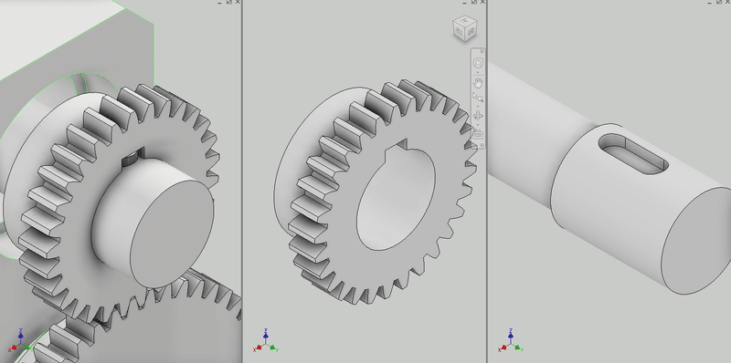
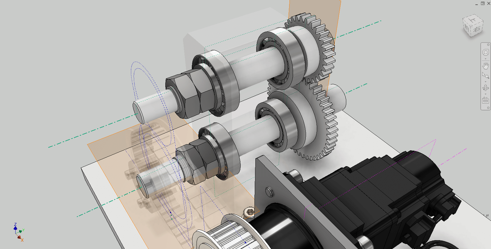
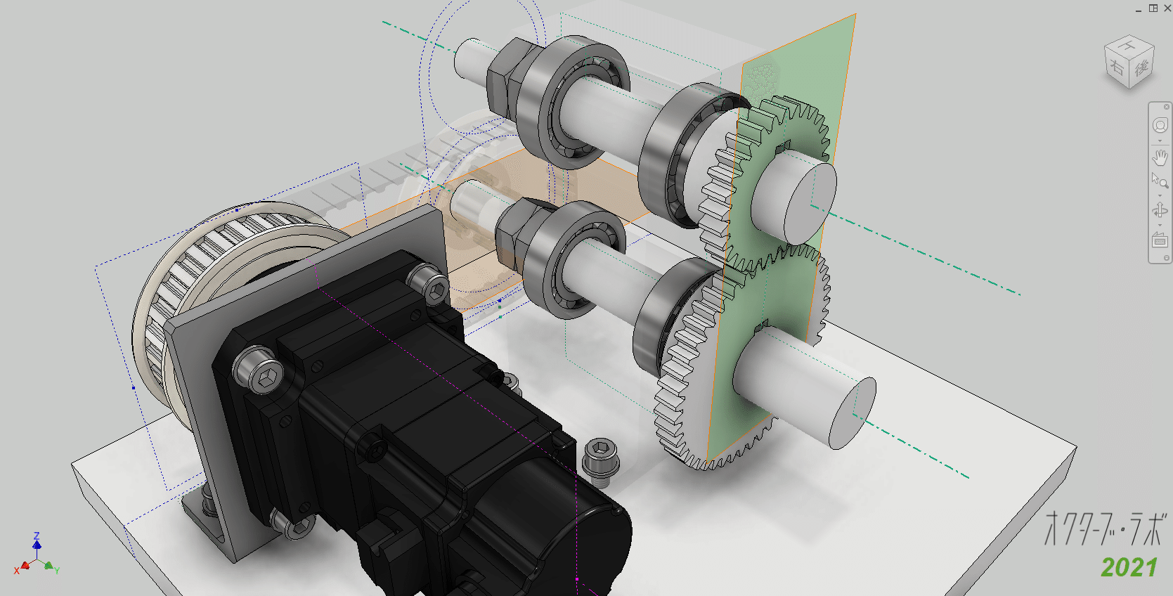
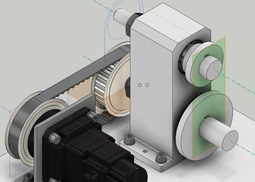
Open the gear template created in the concept design (LOD200) phase. Select Features as the model creation method. When featured, gears are added as features to the existing model (the two parts on the right in the figure). (If you select a component, a new part model will be created.)
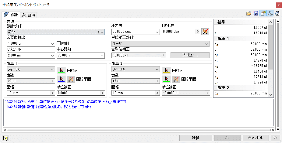
Specify the gear assembly position and perform the calculation.

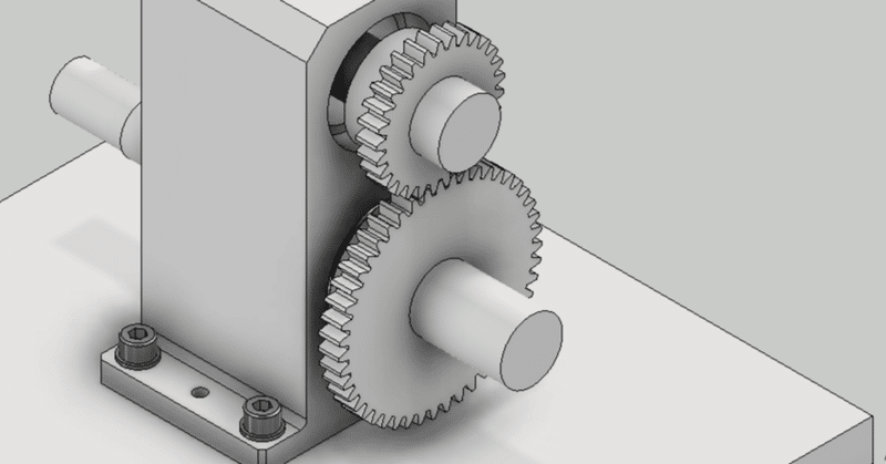
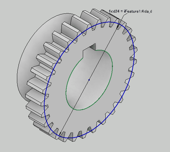
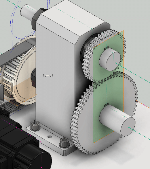
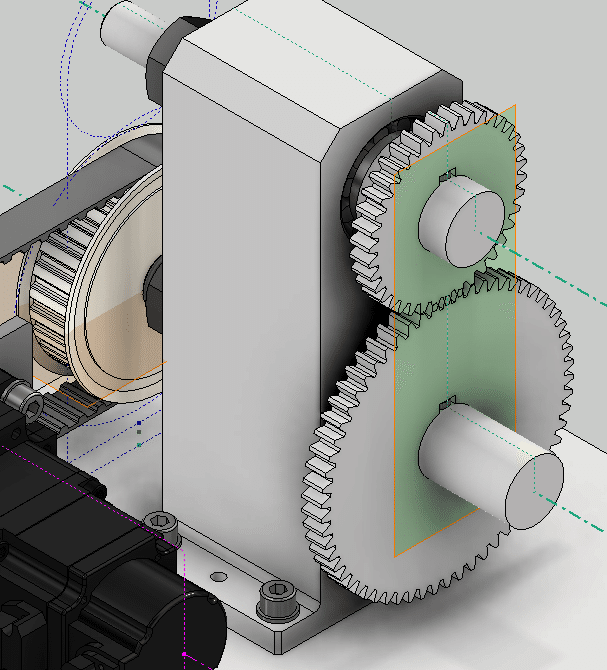
Check the preview. OK to complete the gear model.A tooth profile has been added to the gear parts model.
Let's check the result with a 2D drawing.
I made a video of a series of operations.
Design changes using design accelerators
Design changes are made using the Design Accelerator, similar to the Bolt Fastening Generator.
-
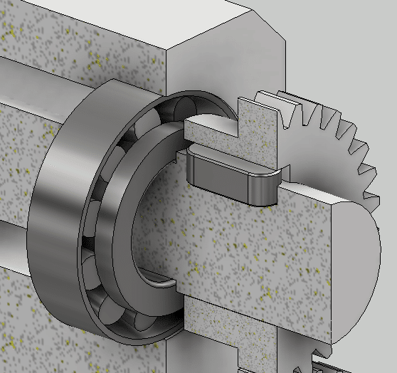
Step 4: LOD300 key
Key
A key is used to transmit torque between the gear and the shaft. The size of the key is determined by the shaft diameter. Dimensions and tolerances are determined by JIS. As an aside, it should be noted that JIS and ISO have different sizes even if they have the same shaft diameter.
Parallel key connection generator
The key design uses a parallel key connection generator.
Run the parallel key connection generator on the assembly model.
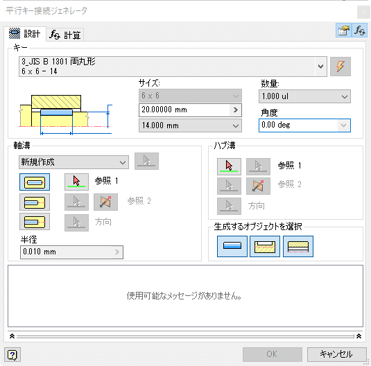
Select the JIS double round key.

Set the key mounting position and size.
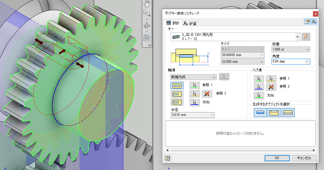
OK
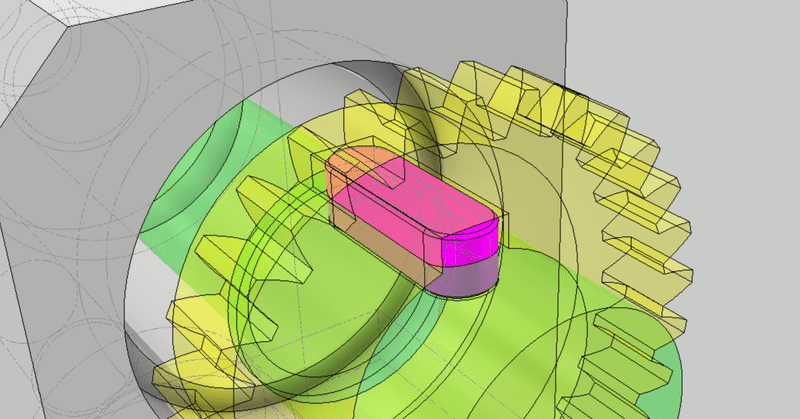
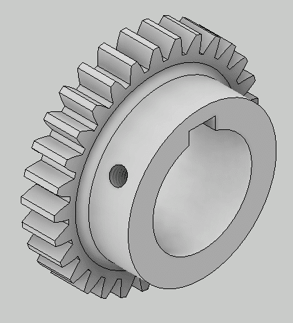
Keyways have been added to the axes and gears, and the keys have been placed in the assembly model.
Add a keyway to the other axis as well.
-
Step 5: LOD300 Bearing
Bearing
Bearings can be placed directly using the Content Center, but it is convenient to place the bearings using a design accelerator. Using the Content Center requires less effort, but there are many types of iMate and it cannot be tied up well. The design accelerator can be placed reliably. Also, even if you make a mistake in the direction, you can easily correct it. Of course, you can easily change the type and size.
Bearing generator
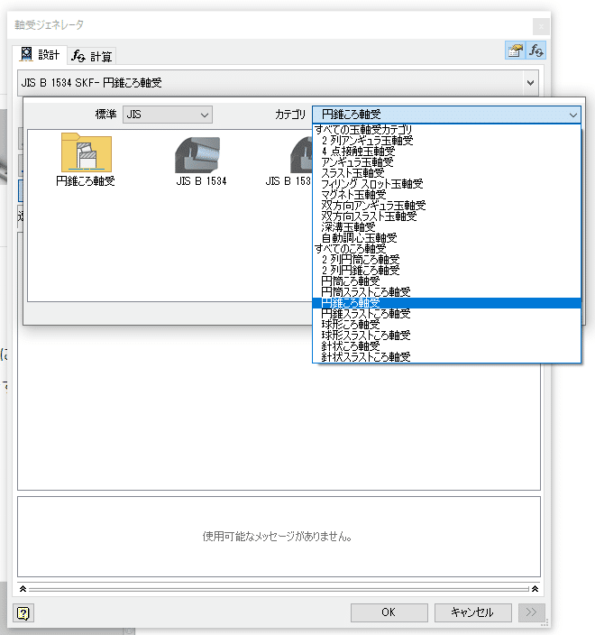
First, choose a standard. Here it is JIS. Next, select the bearing type (here, conical roller bearing) from the category.
Then select the datum for placing the bearings. Select the cylindrical surface (either the shaft side or the hole side is OK) and the end face. Candidate bearings are displayed according to the size of the selected cylindrical surface. A preview of the bearing selected by its name is displayed.
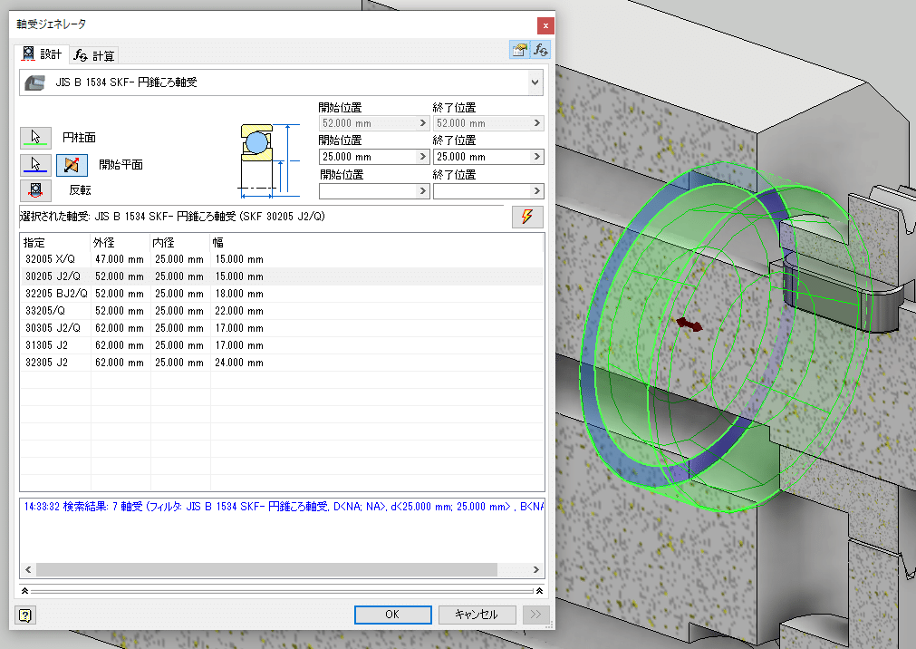
OK will place the bearing.
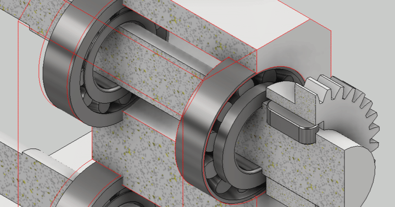
Place the four bearings in the same procedure.
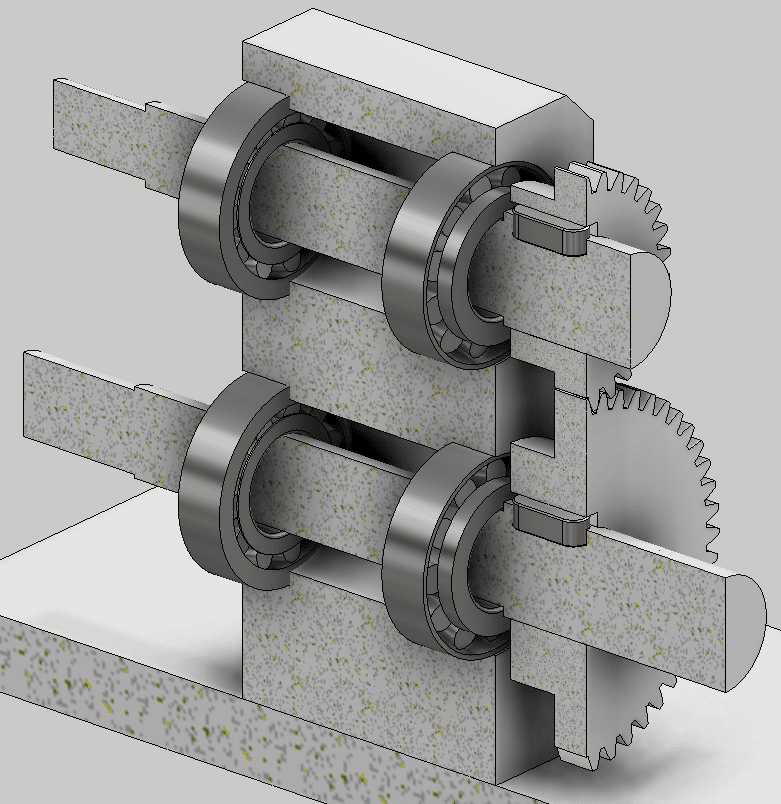
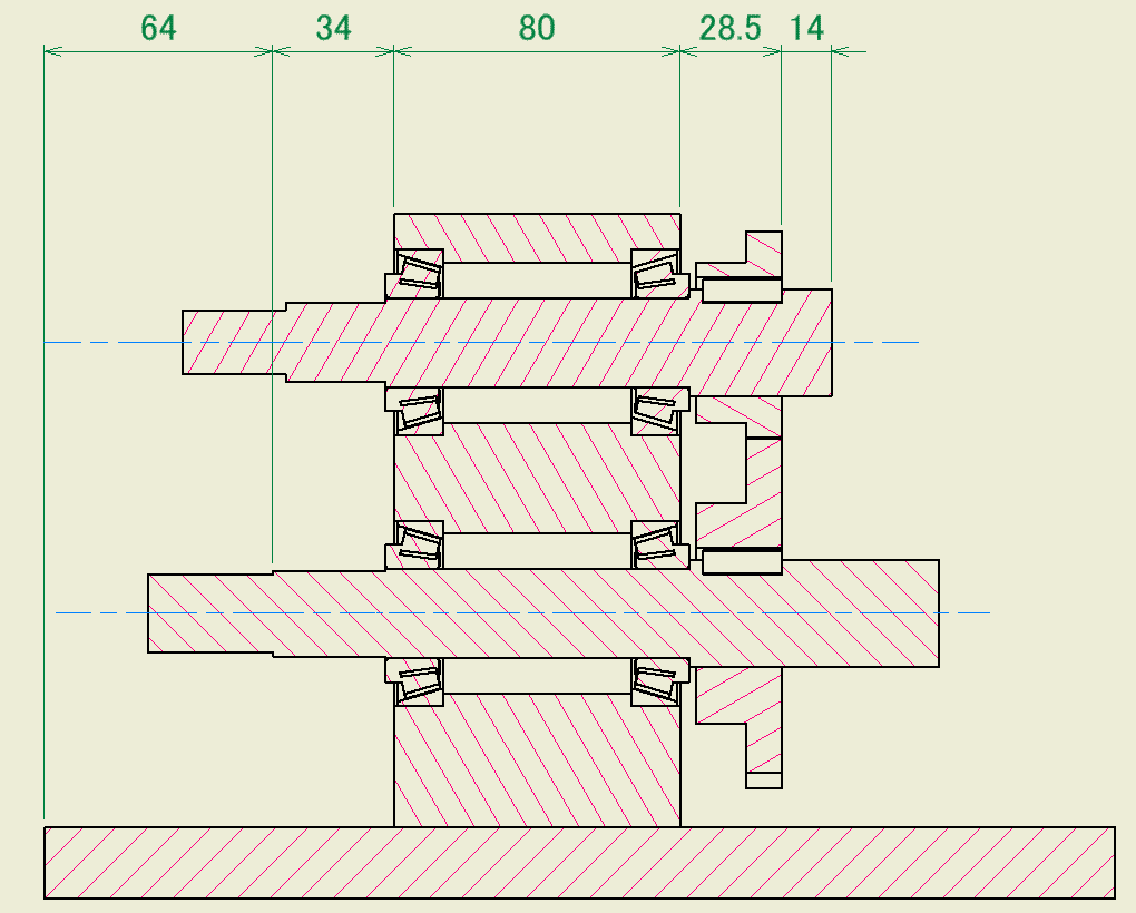
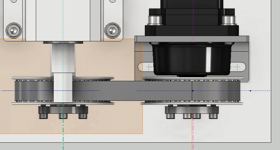
It is easy to understand when the cross section is displayed.
Check the assemblability on the 2D drawing. If there is any interference or gap, go back to the LOD100,200 skeleton and modify the sketch dimensions.
-
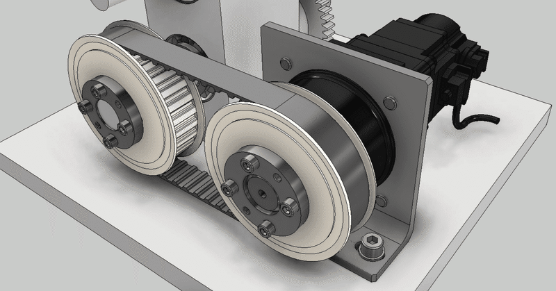
Step 6: LOD300 Detailed design of timing belt and pulley
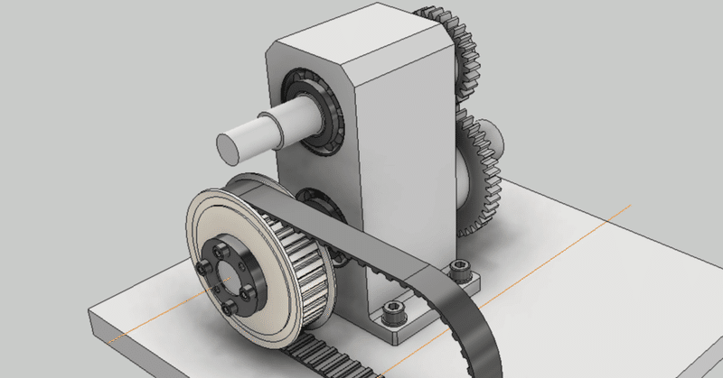
Detailed design of timing belt
We will use the result of the timing belt design check performed on the LOD200. Use the template saved at that time to perform detailed design.
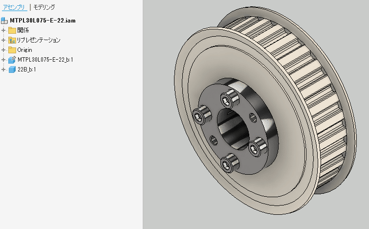
The timing pulley for the timing belt is a purchased item. Selected from Misumi's website. It is also convenient to download as a 3D model. Prepare shaft diameters of 22 mm and 25 mm.
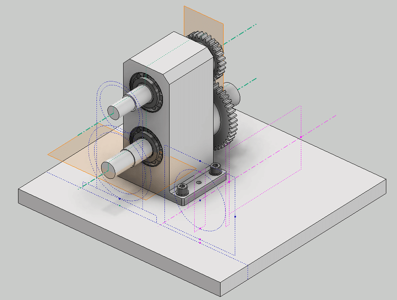
Place the LOD100 skeleton on the assembly model
Place the skeleton on the assembly model as a reference for the placement of the toothed belt. Timing belts and timing pulleys are placed with reference to the geometry on this skeleton.
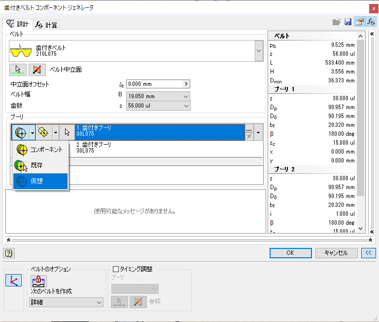
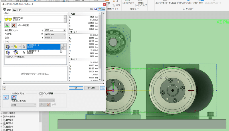
Timing belt placement
Place the timing belt using the saved template. When placing, refer to the geometry of the skeleton model.
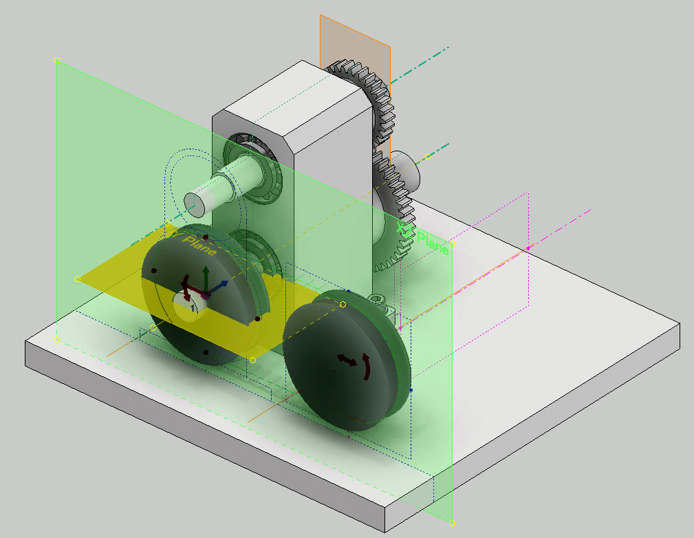
Since the pulley will be placed later, select virtual. If you select Details in the belt options, the tooth profile will be displayed on the belt.
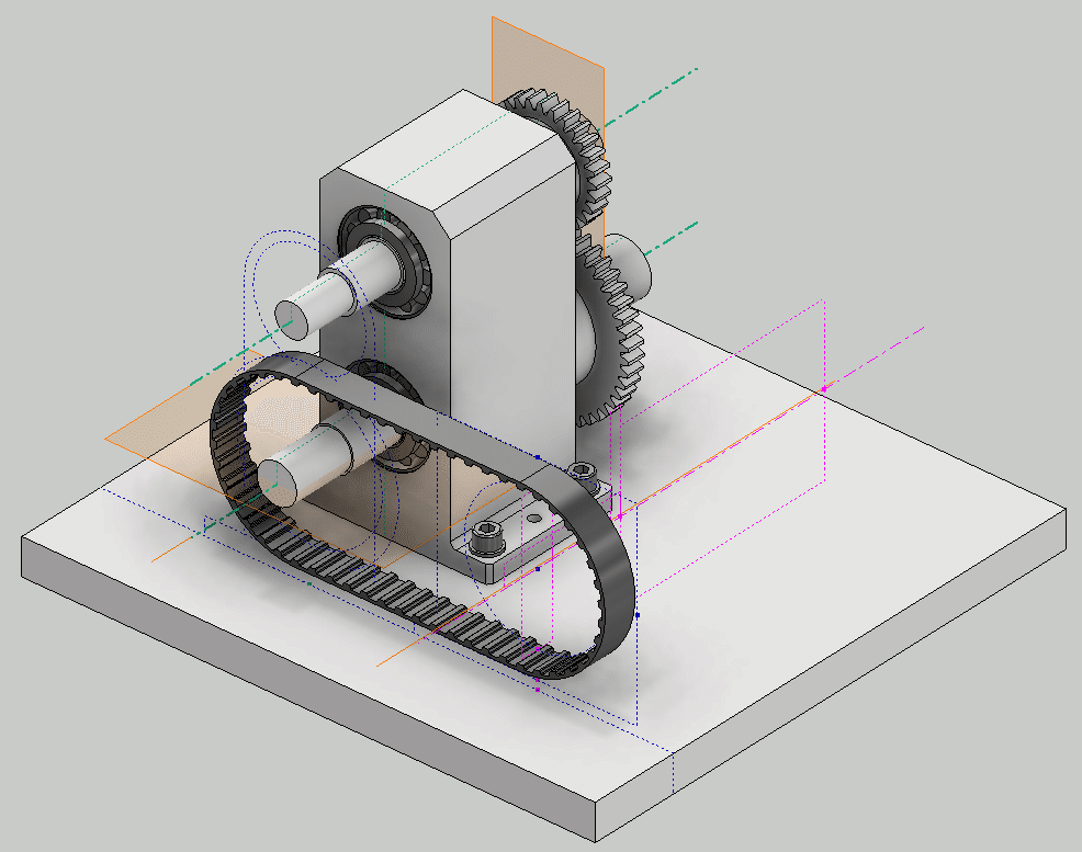
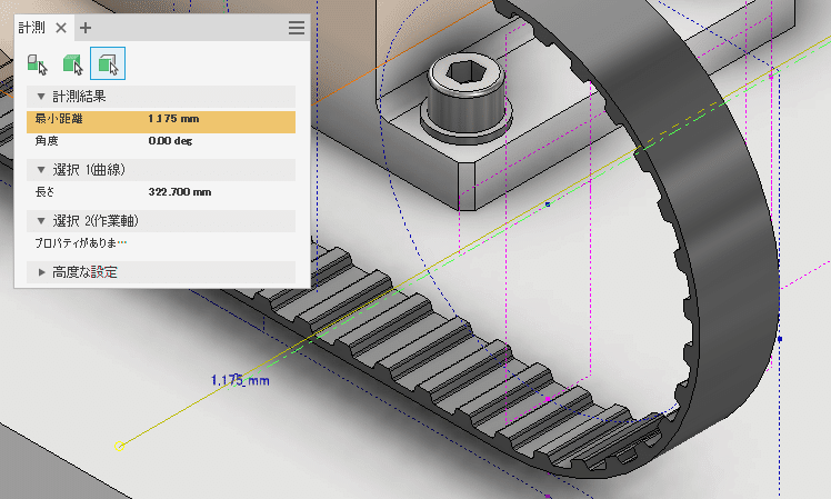
The length of the timing belt is not a good value. The position of the drive shaft deviates slightly from the position of the skeleton. This deviation will be adjusted by making a slot in the motor mounting bracket.
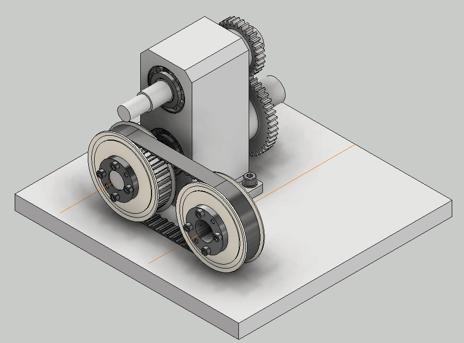
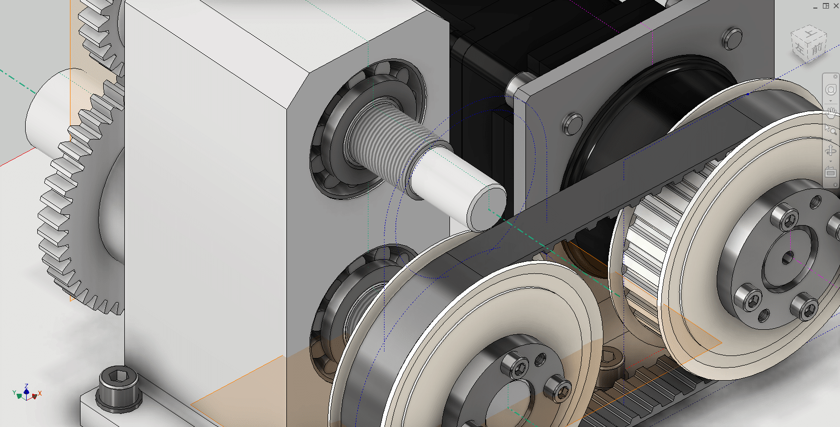
Arrangement of timing pulley
Hide the skeleton once to avoid confusion. The pulley is placed with reference to the geometry of the timing belt.
Place the timing pulley in a suitable position. Then, from your browser, check the geometry to use for the constraint.
Place using constraints. Please refer to the video.
Follow the same procedure to place the timing pulley on the drive side.
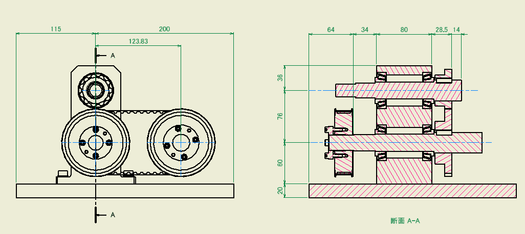
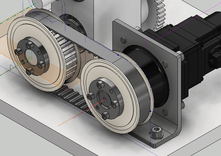
Confirmed with 2D drawing
Check in the 2D drawing.
-
Step 7: LOD300 Servo motor installation
Install the servo motor according to the position of the timing pulley.
First, create a subassembly model that includes the servo motor and mounting bracket. The next step is to constrain the assembly model to the timing pulley and base plate.
Servomotor
For the servo motor, use the original model referenced in GrabCAD.
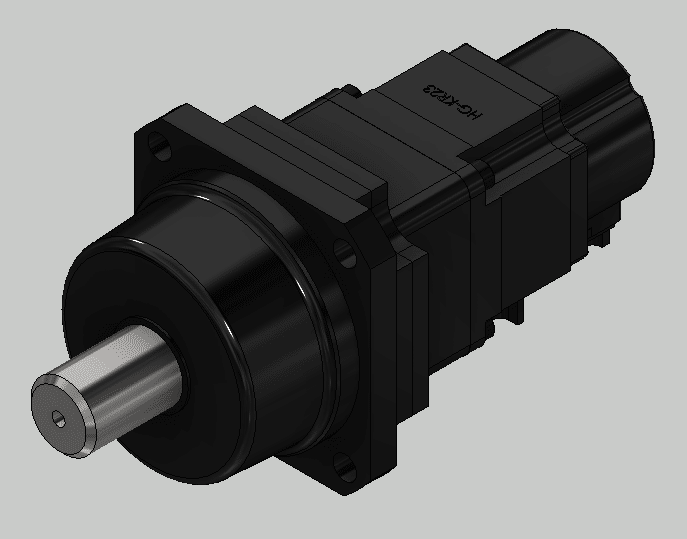
# Mitsubishi HG-KR23G1-1.5 Servo Motor.iam
This model is a STEP file. There are mounting holes in the gearhead parts, but they are not recognized as hole features. Therefore, add a sketch and place a point at the hole position.
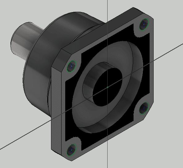
Creating a servo motor assembly
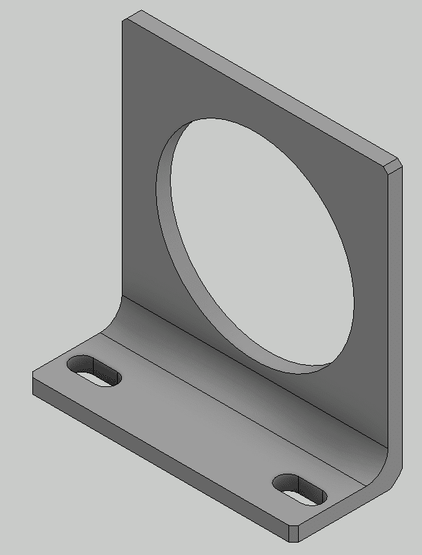
Create a motor mounting bracket from the LOD200 skeleton.
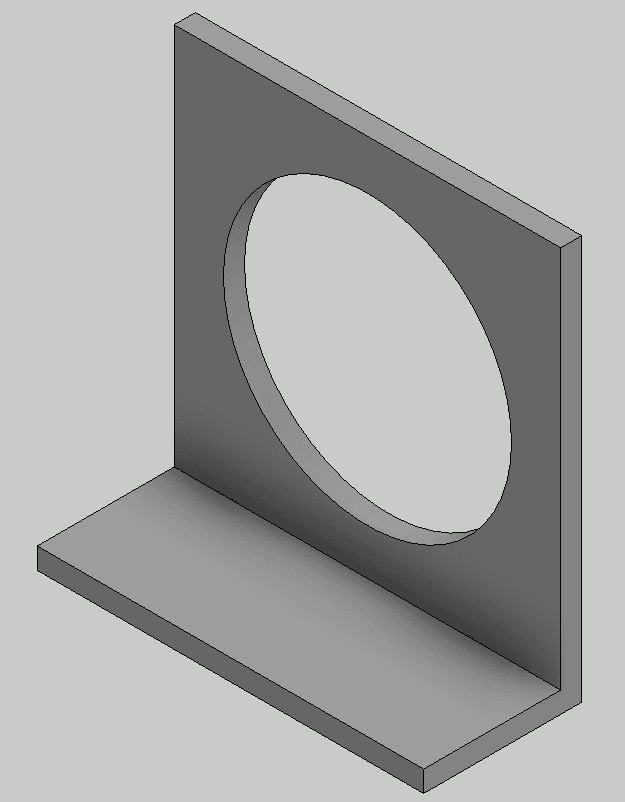
It is made by bending a plate with a thickness of 9 mm. The motor mounting holes will be drilled later using a bolt fastening generator.
Create a new assembly model and place the motor mounting bracket at the origin.
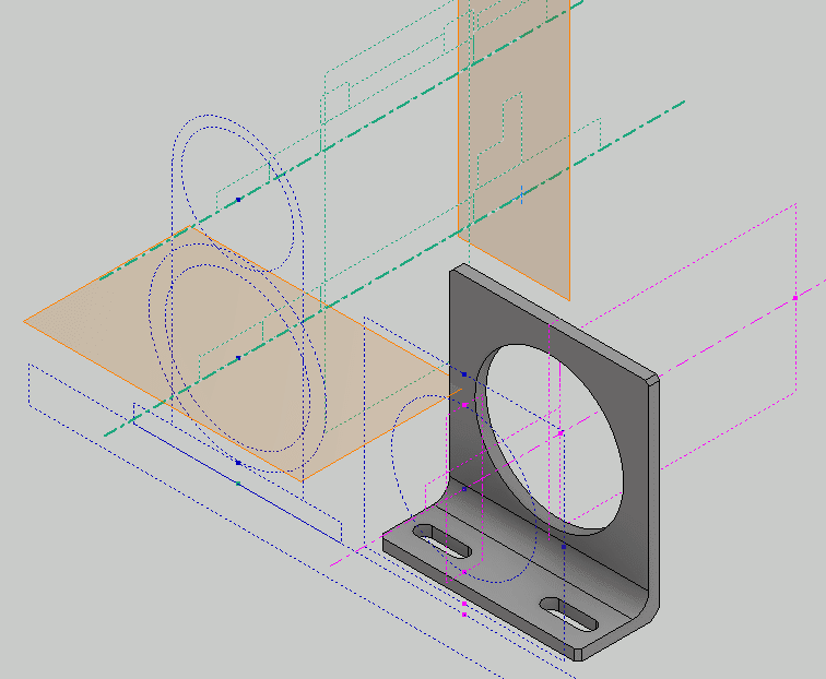
Placed at the origin. Skeletons are placed for comparison, no placement is required in the actual design.
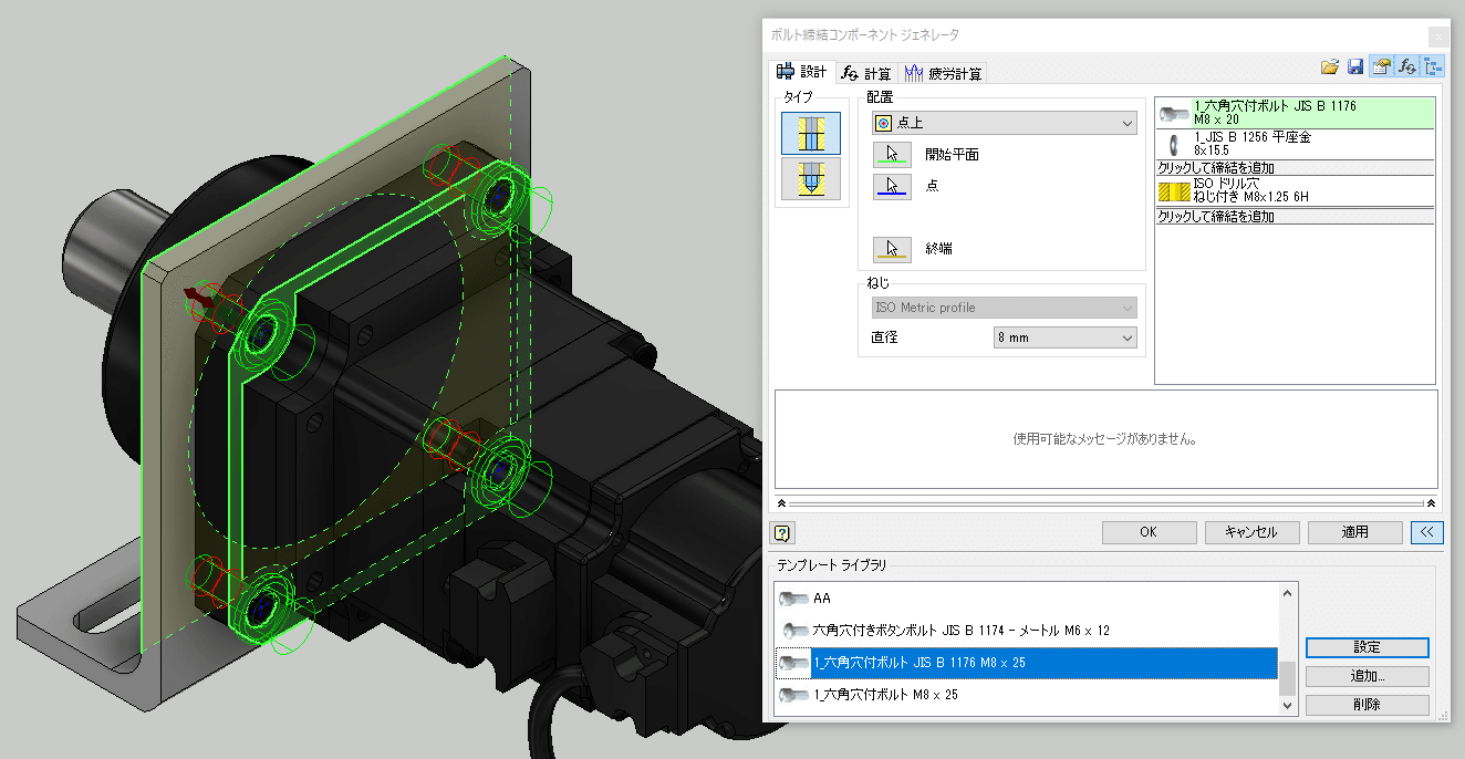
Mount the servo motor on the motor mounting bracket. It is constraint by the rigid of the joint.

Place the bolts using the bolt fastening generator. At the same time, mounting holes are created in the motor mounting bracket.
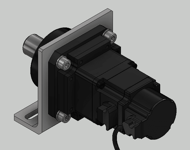
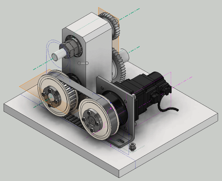
Servo motor assembly placement
Install the servo motor assembly on the drive unit. Constrain the skeleton and timing pulley shafts and the motor shaft, and constrain the bottom of the bracket and the top of the base plate. The axial direction of the motor is constrained to the sketch of the skeleton.
* It is also possible to restrain the components between the skeleton and the servomotor assembly, remove the restraint in the mounting direction, and restrain the shafts. This may be easier to understand later.
Use the bolt fastening generator to place the bolts on the bracket base plate. The location of the holes in the base plate is specified using the skeleton sketch.
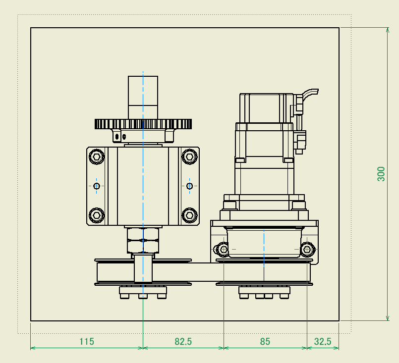
Finaly, Check in the 2D drawing.
-
Step 8: LOD300 Detailed design of output shaft and related parts
Finally, make Detailed design of output shaft and related parts. This completes the design of the 3D model.
Detailed design of output shaft
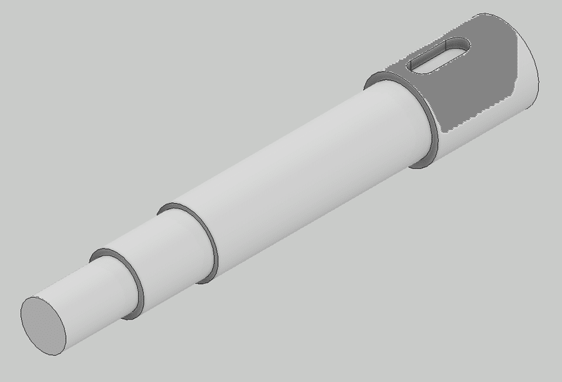
The keyway has already been created in STEP4.
Add a detailed shape to the output axis. Add fillets and chamfers. Also, add a fine screw for the nut.
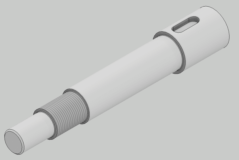
Fix the bearing with a double nut
Place a Type 3 nut from the Content Center. Make sure the screw is a fine screw. And place it. Since there is still a degree of freedom in the direction of rotation just by arranging it, use angle constraint to fix it in a good-looking position.
Detailed design of gears
Add the detailed shape of the gear. Add fillets, chamfers, and machine screws for fixing.
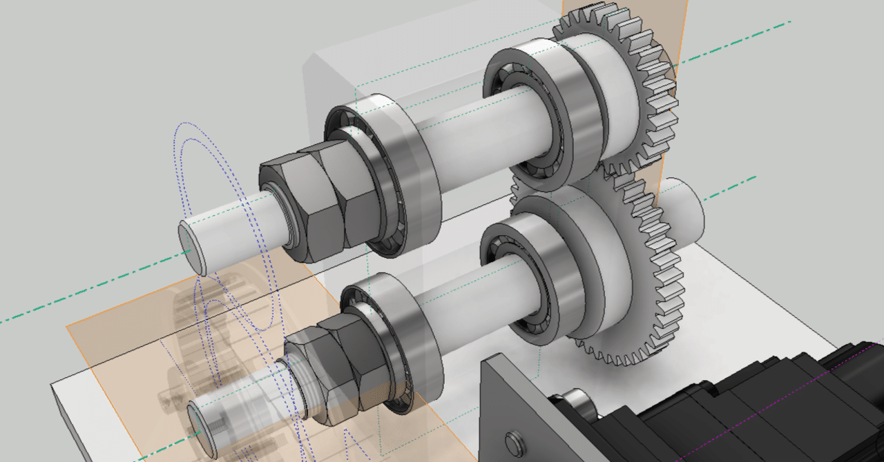
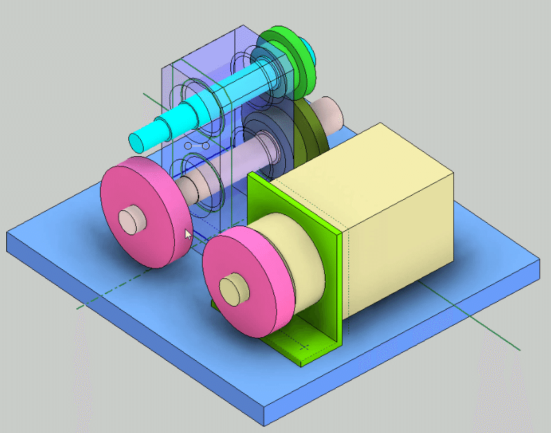
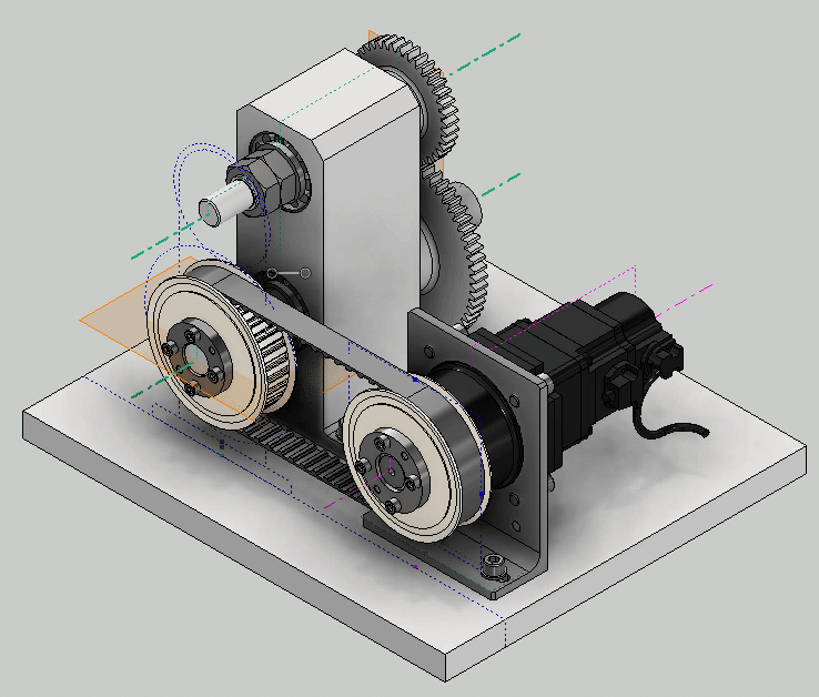
Completion of assembly model
Bearing blocks are transparent for easy understanding
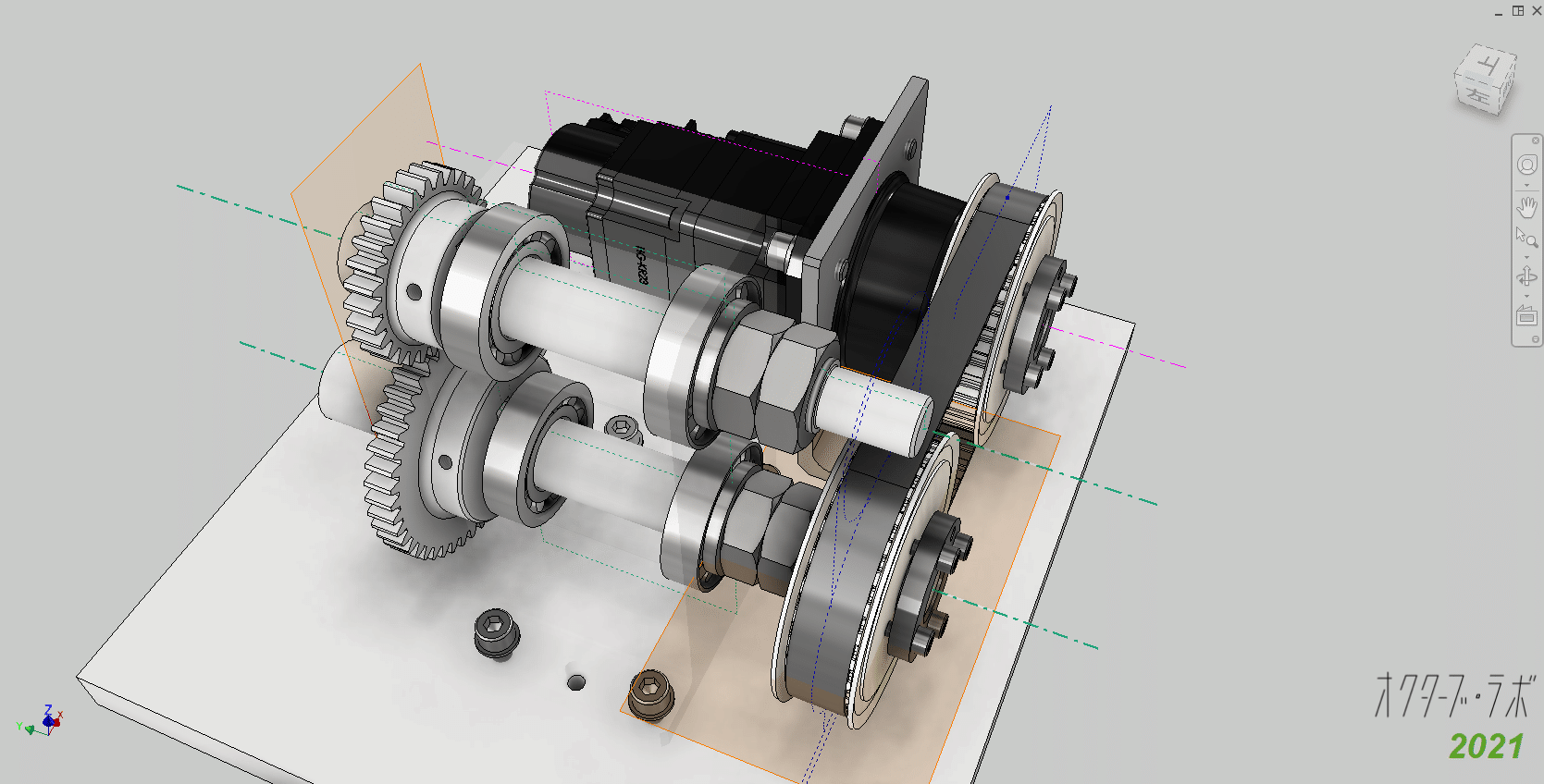
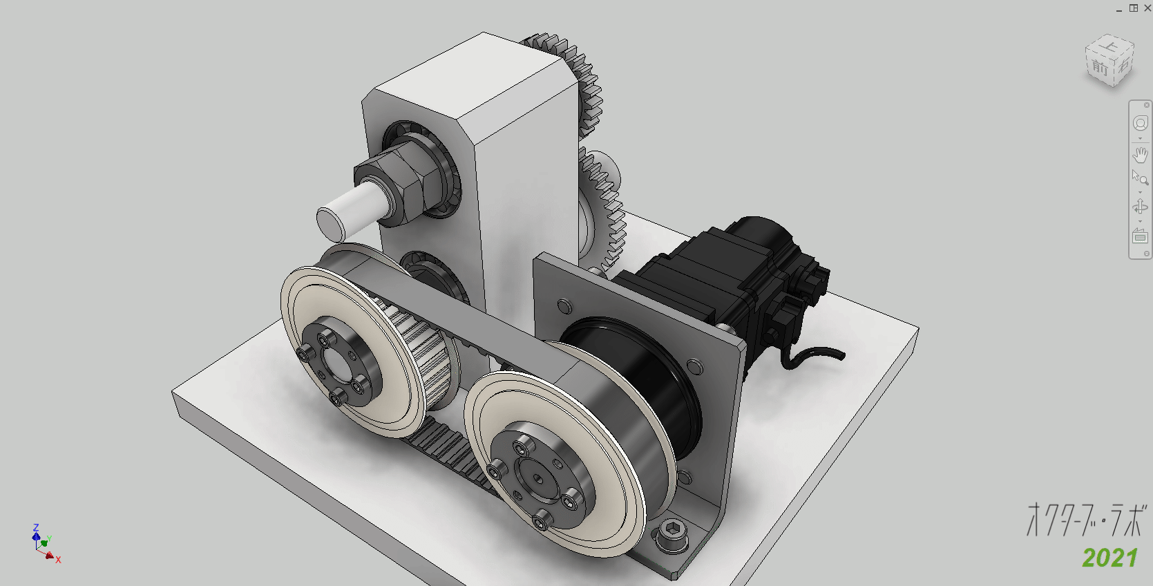
Completed by hiding skeletons and working objects.
Confirmed with 2D drawingConfirmed with 2D drawing
-
Step 9: LOD300 2D assembly drawing
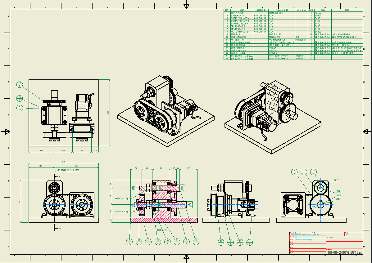
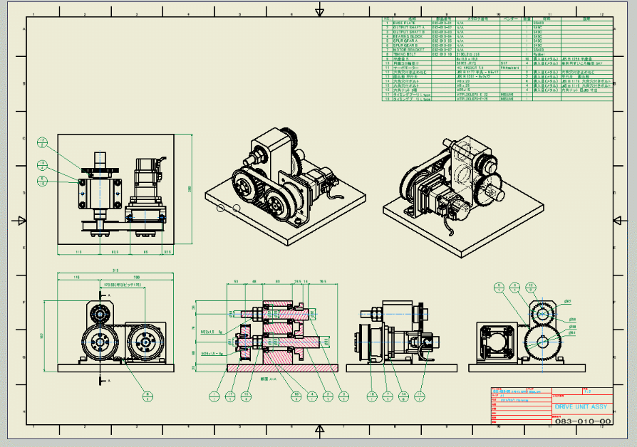
Complete the 2D drawing.
As explained so far, even while creating a 3D model, the 2D drawing is updated from time to time, so the following drawing is created. I will complete the drawing based on this drawing bellow.
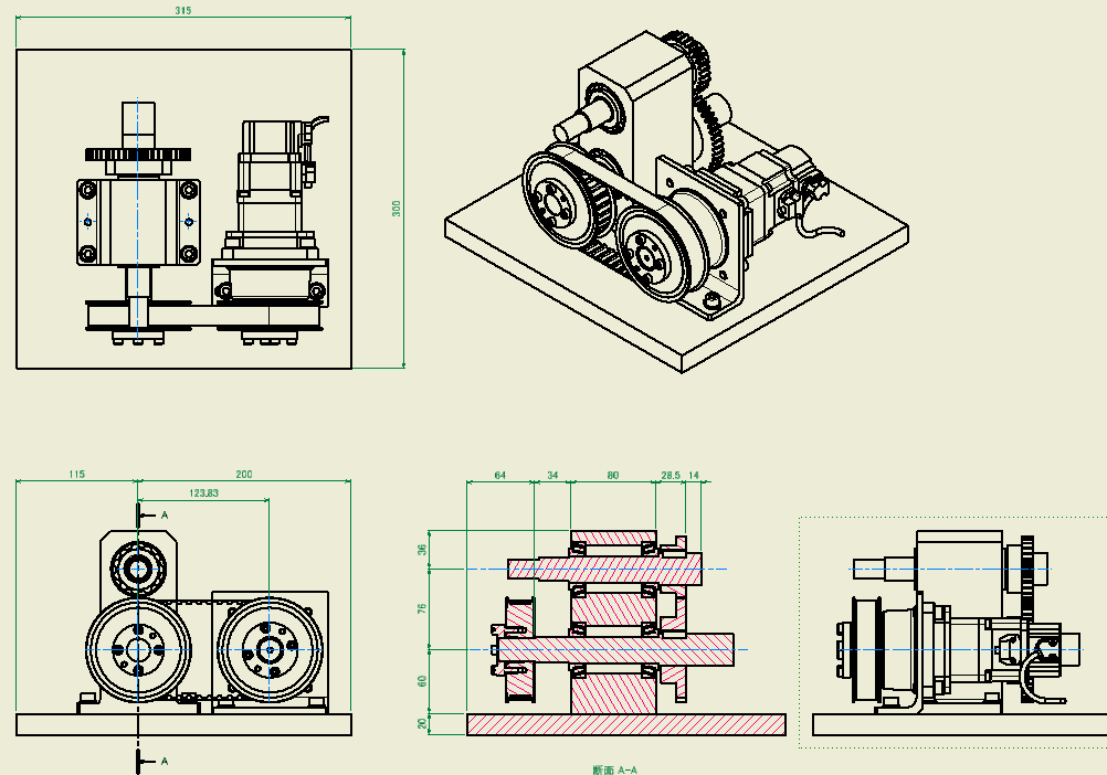
Layout
A1 size, scale 1/2, front view, plan view, right side view, cross section of output axis, rear view, isometric view (2 places) are arranged as shown in the figure. Make sure you can afford to fill in the dimensions and balloons.
This layout is good because it meets the requirements.
In addition, the isometric view on the back will be better if you can see the connection of the output shafts.
Unhide the bearing block in cross section. is. Based on this drawing, I will complete the drawing below.
Dimensions, notes
Add dimensions and notes. It also adjusts their positions. If you don't have enough space for the dimensions, adjust the layout of each view.
Spur Gear
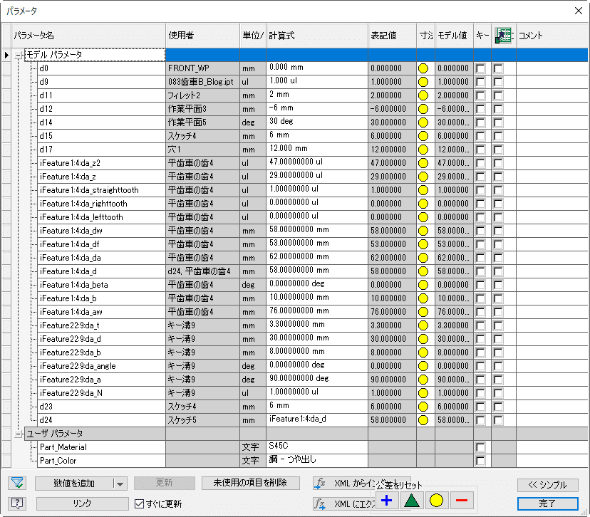
Displays the pitch circle of the gear. To do this, add a sketch showing the pitch circle to the spur gear parts model in advance.
I will explain how to modify the parts model.
Open the gear parts model.Create a new sketch on the end face of the gear, create a sketch circle concentric with the hole, and select the dimension from the parameters. Since we are designing with a spur gear component generator, the gear properties are registered in the parameters. Use the value of this parameter.
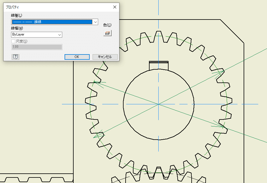
This is a method to display the pitch circle on the drawing.
Select Include Model Sketch to display the sketch. Then use the properties to make the linetype a dashed line.
Balloons and parts list
Add balloons and parts list.
This is complete.
3D Viewer
The completed model can be viewed from the link below.
-
Step 10: Diversion design using top-down design method
Based on this drive unit, I will try to divert it. It uses a top-down design method, so you can work efficiently.
Design specification
We will design a modified version of the following two specifications.
- Changed the nominal pitch of drive shaft and output shaft from 125 to 160
- Changed the distance between the output axes from 76 to 100
Preparing for duplication
Prepare a copy of the original drive unit using Vault's copy design or Inventor's Pack & GO feature. (The explanation of the procedure is omitted)
Open the duplicated assembly. Make sure you haven't accidentally opened the original model.
LOD100
Open the skeleton of LOD100 and change the specifications.
From
To
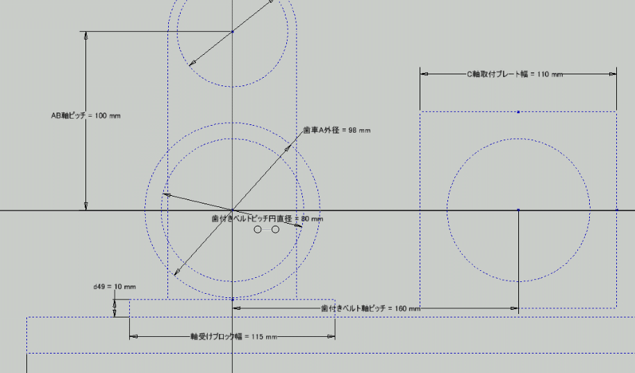
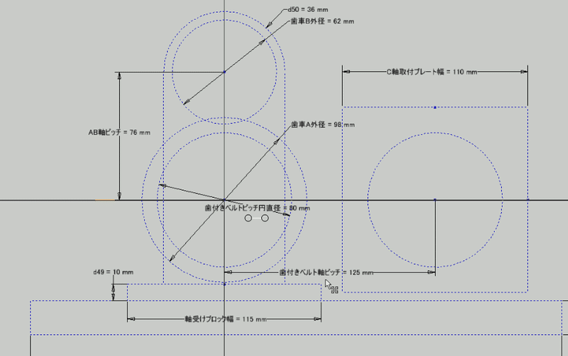
LOD200
The LOD200 skeleton will be automatically modified as shown.
From
To

Confirm that the gear needs to be redesigned, the tap hole position needs to be corrected, and the toothed bell needs to be redesigned.
LOD300
Since the model of LOD200 has been changed, the detailed model of LOD300 has been changed as follows.
The motor assembly is constrained to the axis of the timing belt, so the position has not changed. Only the tap hole position has been changed. Therefore, we will redesign the timing belt using the design accelerator.
Timing belt redesign
From the browser, select the timing belt and execute "Edit with Design Accelerator".
Change the number of teeth to 64 to match the pitch. Then, the position of the motor assembly changes according to the axis of the timing belt.

Spur gear redesign
Similarly, use the spur gear component generator to redesign the spur gear. Select the spur gear from your browser and perform "Edit with Design Accelerator".
Then, a warning is displayed that the distance between the centers is different from the setting. If you change the center distance to 100 and perform a recalculation, the warning disappears.

The tooth profile has disappeared because the diameter of the outer diameter circle of the gear has not been corrected.

The tooth profile is displayed. But this time it is interfering with the base plate.
Change of axis height
To avoid interference between the gears and the base plate, open the LOD100 skeleton and change the shaft height from 60 to 80.

There is no interference.
The shaft height of the motor assembly has also been changed correctly.
Correction of tap hole position
Use the bolt fastening generator to correct the tap hole position.

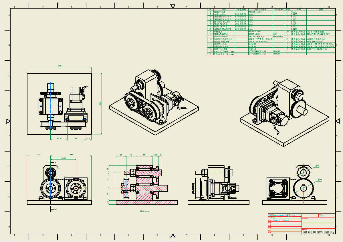
Check the change result in the 2D drawing
Make sure the changes are correct in the 2D drawing.
From
To
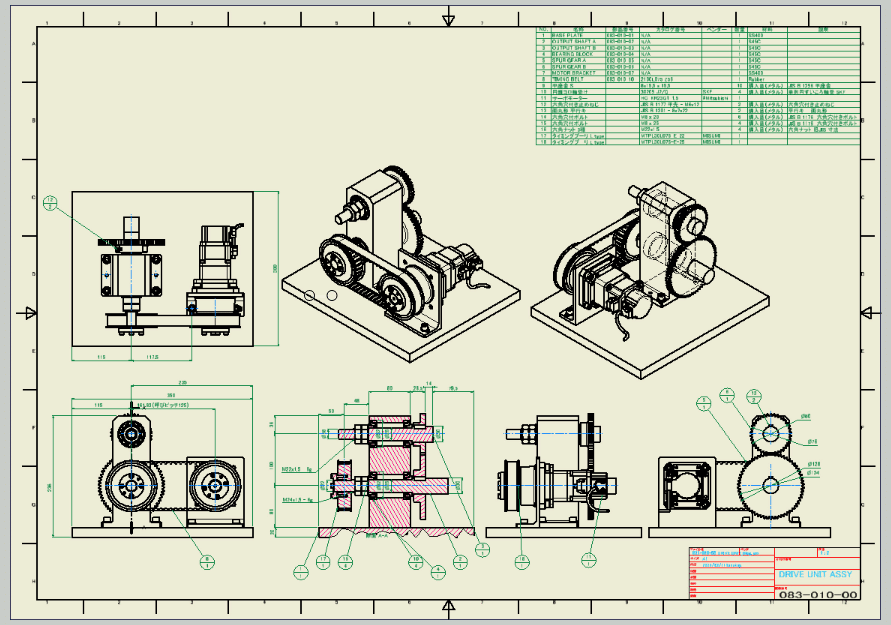
It is completed by aligning the dimensions and the position of the balloons.
Summary
If you use the top-down design method for 3D design, you can easily design for changes and diversions. If you are interested, please apply it to your own design.
This time, I focused on the introduction of the procedure. In reality, it is necessary to verify the strength and engagement.
Please refer to the video for the procedure of diversion design.
This concludes the explanation of the drive unit design procedure.
Comments and questions are welcome, so please comment at that time.
Thank you.
