

Using Solidworks Configurations In Parts And At Assembly Level

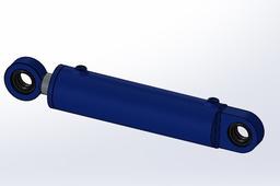
Using this Example of a Basic Hydraulic Ram.
An easy to follow tutorial on creating and enabling part configurations and how to follow them through to assembly level resulting in more diverse parts and dynamic 3D models.
-
Step 1: Find Configurations Option
 At the top of the feature tree you will find the configuration tab select and right click the space where the feature tree usually is then select add configurations.
Give your configuration a name then select the green tick.
-
Step 2: Edit Part Features
Now to make each of your configurations unique.

You are now able select the configuration you want to edit in the configurations tab and change dimensions , extrudes also create and supress features without effecting your original part .
 With the configuration you want to edit selected go into the dimension you want to modify at the end of the dimension input box select the small drop down .
Solidworks has a little glitch the options aren't showing but they are there.
At the top is for this configuration only
second is for all configurations
last is specify configurations
I want to make the bore of this cylinder larger so I increase the dimension with the for this configuration option selected.
To avoid the glitch use the options shown below.

The process is much the same to adjust extrudes and cuts within your configurations.

Don't forget you can create new features or supress existing ones for each configuration .
Once you have created a few configurations you will now be able to switch between them in the configurations tab.


In the picture I have used the specify configurations to include all of the extra features of the other configurations so its bigger in the bore size , longer and has bigger ports.
-
Step 3: Using Configurations at Assembly level

In the same way as part level add in some configurations into your assembly.

And name your assembly configuration.

To bring the part configurations up to assembly level right click the part in the feature tree and select properties.

This is where you can select which part configuration to add to the assembly level configuration you currently have selected.
This also works with sub- assembly's within a larger assembly.

This is all about getting the right part configurations to match the assembly configurations.
You will be able to switch through your assembly configurations in the configurations tab.


Here I have added the properties of the other configurations using the specify configurations option.

you also can include new parts or suppress existing parts in each assembly level configurations in the same way as you did at part level.
Insert your new component as normal it will only show in the configuration you have selected and will be suppressed in all the others until you unsuppress in each configuration.
This method works with mates as well including, advanced and mechanical mates.


The possibilities are end less.
-
Step 4: Configurations in Drafting
You will be able to access your configurations in your technical drawings making it easy to compare assembly positioning and switch through configurations so they don't need to be loaded into your drafting sheet individually.

Just use the drop down in reference configuration .
-
Step 5:
 Please like , Share and comment if you have found this tutorial helpful.
